Welcome to my speaker impedance equalization (Zobel network) and resonant frequency filter calculator.
I’ve also provided plenty of helpful information:
- Understanding what speaker resonance, speaker impedance curves, and why they matter.
- What to do if you don’t have the technical specifications for your speakers.
- Additional tips to know.
Note: Javascript must be enabled in your browser to use the tool.
Contents
- ZOBEL NETWORK & SERIES NOTCH FILTER CALCULATOR
- Speaker resonant frequency and impedance basics explained
- Speaker parameter examples and basics to know
- How impedance compensation and series notch filters help audio performance
- Should you always add a Zobel network or a resonant notch filter?
- What if I don’t have the specifications for my speakers?
- Capacitor, inductor, and resistor component tolerances and price level
ZOBEL NETWORK & SERIES NOTCH FILTER CALCULATOR
HOW TO USE THE CALCULATOR:
1. Choose a parameter type:
- If you have speaker parameters from the manufacturer, select Enter my values (this is the default & recommended setting).
- If you do not have any information, you can select example speaker parameters to get a reasonably close result for unknown speaker drivers. Preset values from real speakers will be used.
2. Choose the calculator accuracy type: Simplified or Advanced:
- Simplified: requires only 3 speaker parameters: inductance “Le“, DC resistance “Re“, and the resonant frequency “Fs.”
- Advanced: for greater accuracy, you can enter Qes and Qms Thiele/Small values.
(Note: Simplified mode will give a fairly accurate result, so this isn’t critical.)
3. (OPTIONAL) Resonant Ohms value:
- For simplified mode, if you know the peak Ohms at the resonant frequency, you can optionally enter it for a more accurate Rnf result.
4. Enter the values as required: Use milliHenries, microFarads, Hertz, and Ohms.
The calculator will output:
- Zobel network values Cz (in microFarads) and resistor Rz (in Ohms).
- Series notch filter values Cnf (microFarads), inductor (milliHenries), and the optional Rnf value (Ohms).
Note: Rnf is normally = the approximate rated speaker impedance in Ohms (4Ω, 8Ω, etc.).
Speaker resonant frequency and impedance basics explained

Understanding impedance
First, a speaker’s impedance is its total opposition to the flow of electrical current when a voltage is applied. This means it isn’t just the resistance in the wound wire that forms a voice coil: it’s the algebraic sum of both the resistance and the inductive reactance.
At low frequencies, the total impedance will be about the same as the direct current resistance (DCR) you can measure across the voice coil with a test meter. However, as an audio signal is applied, the greater the frequency, the higher the impedance will be due to the inductance created by the voice coil windings.
Image: Diagram showing a speaker voice coil which is a tightly wound coil of conductive wire. Coiled wire has a property called inductance that affects the opposition to current flow as the frequency changes.
Speaker impedance curves
Speakers aren’t perfect in that due to how impedance works, all speakers that feature a wound wire voice coil have a non-flat impedance curve. When measured with a speaker measurement tool, most speakers will have an impedance curve graph like that in the example image above.
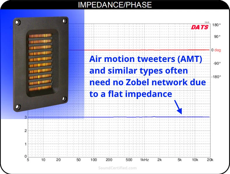
A few types of speakers, like planar ribbon tweeters, do have an essentially flat impedance line, however, since they use a different type of motion design, unlike cone speakers.
Speaker resonance and peak Ohms at the resonant frequency
Speakers using a voice coil also have an interesting behavior: at a center frequency called the resonant frequency, both the mechanical parameters (magnet and speaker cone + bobbin assembly) and electrical properties react and show a peak impedance above the manufacturer’s Ohms rating.
In other words, the mechanical characteristics of the speaker assembly at this particular frequency show a behavior in which the speaker’s normal “control” over the magnet/cone assembly is lesser than normal. This allows a high peak in the Ohms value to occur.
While it’s normal for speakers with a magnet & voice coil assembly (including woofers, midrange, and tweeters), it isn’t necessarily an impact on sound performance. The impact of a speaker’s resonant frequency depends on both the speaker and its particular use.
I’ll cover this in more detail later.
Speaker parameter examples and basics to know
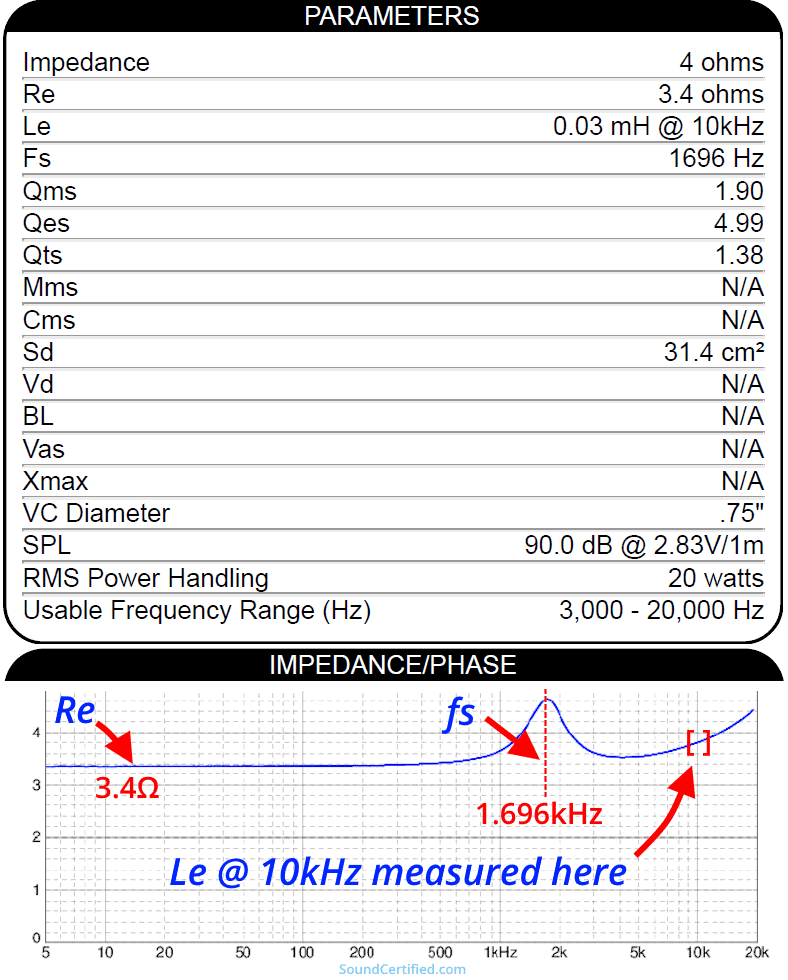
Manufacturers sometimes provide the speaker parameter specifications you’ll need to design a Zobel impedance equalization network, a series notch filter, or other speaker-related design.
Sadly, while they’re fairly common with 8 Ohm home stereo and hi-fi speaker drivers, they’re much less common with car audio drivers. The good news is if you’re dedicated to better sound, it’s possible to find (or verify) speaker parameters yourself with a handy tool like the Dayton Audio DATS test device.
How impedance compensation and series notch filters help audio performance
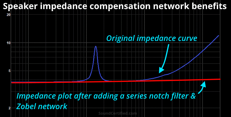
Speaker impedance networks can greatly benefit the performance of even budget speaker units by correcting their rising impedance due to the voice coil inductance. They’re primarily useful for tweeters and midrange speakers.
They offer several benefits despite being so inexpensive and simple to implement:
- Tweeters have two direct benefits: reducing harshness and ensuring L-pads or resistor networks for volume attenuation work properly.
- Prevents negative effects (shifting) on passive speaker crossovers.
- Helping stabilize speaker response affected by having a non-flat impedance behavior.
Speaking of L-pads, if you’d also like to tame harsh tweeters or other speakers, check out my handy L-pad calculator as well.
What are Zobel networks and how do they work?
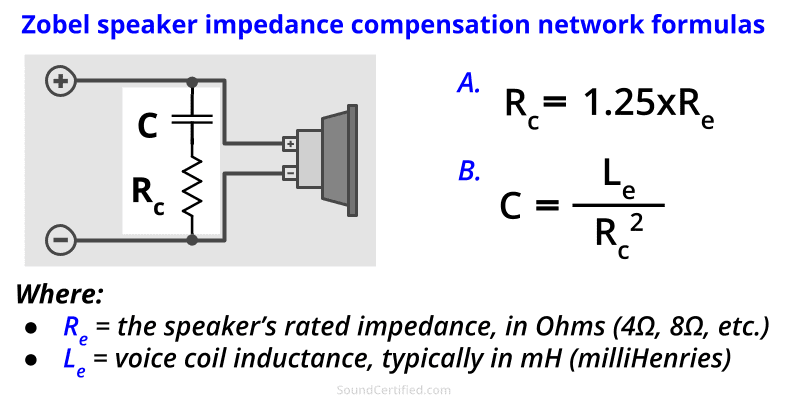
A Zobel network is a simple CR (capacitor-resistor) filter added in parallel to a speaker driver to flatten the total Ohms impedance load at upper frequencies. In the case of a loudspeaker, this is done by canceling out the effects of inductance in the voice coil.
Technically speaking, Zobel networks (named after Otto Zobel of Bell Labs) can consist of a variety of filter or resistor networks for various applications. For audio applications, however, we’re generally only referring to a simple C-R design.
Zobel network mathematical formulas
Calculating capacitor and resistor values for building your own Zobel network is pretty simple – just a bit of basic math is needed.
- Resistor Rc is close to, but slightly higher than, the speaker’s voice coil resistance Re. A factor of 1.25 is used; this is because when resistance is in parallel, the total is always less than the smallest resistor.
- The capacitor value depends heavily on the inductance of the voice coil (Le) because it works to counter the rise in impedance.
Series notch filters and what they do
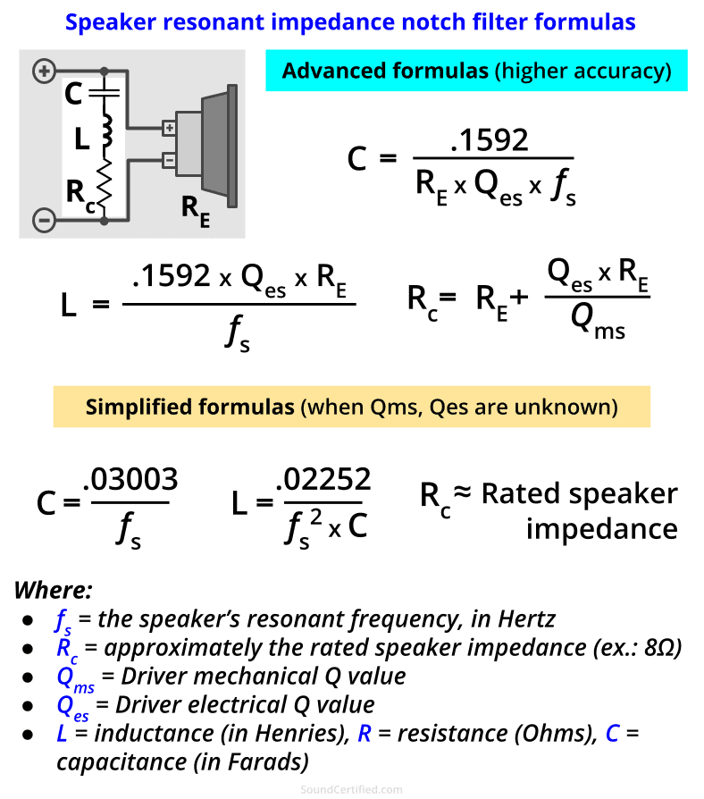
Series notch filters use an LCR (inductor, capacitor, and resistor) network to tame the high impedance peaks that occur. Inductor-capacitor networks act as a bandpass filter and work with the resistor Rc together.
Resonant LC circuits have a unique property in that they can be used to affect the speaker impedance for only a limited range of frequencies. Since the resonant peak occurs only around the resonant frequency Fs, this is perfect. The speaker’s normal functionality won’t be affected outside of this limited band of frequencies centered around Fs.
Here’s how a speaker series notch filter works:
- Outside of the resonant peak range, the LCR circuit has a very high total impedance, meaning it has virtually no impact on the speaker load or amplifier.
- At the resonant frequency, the LC series impedance is at its lowest (close to zero) and resistor Rc will be in parallel with the speaker. (Much like a Zobel network is used to equalize a speaker’s impedance rise.)
- The parallel circuit Rc with the peak Ohms impedance will result in a total Ohms load approximately that of Rc.
- The amplifier, speaker crossover, or other components will see an essentially flat Ohms load at Fs.
Series notch filter math formulas
Don’t be afraid of the math! While it can look a bit intimidating, it reality it’s mostly just some multiplication and division. While the advanced formulas use parameters Qms and Qes are pretty accurate, they’re not critical. If you don’t have access to those you’ll still get pretty good results with the simplified formulas.
For the simplified version, we use the approximate rated impedance of the speaker (4Ω, 6Ω, 8Ω, etc.). The total impedance will be just slightly less than the resistor value. If you’d prefer to keep the total load around the value Re, you can use a starting point of about Re x 1.25. Trial and error may be needed if you’re after the best accuracy possible.
In that case, changing Rc in increments of 0.5Ω would be a good approach.
Should you always add a Zobel network or a resonant notch filter?
When to use a series notch filter
Series notch filters are generally beneficial when:
- Midrange and tweeters are used. These are the most sensitive to performance issues caused by resonance – especially when more advanced 2-way or 3-way crossover designs are used.
- The driver doesn’t have Ferrofluid in the magnet/voice coil assembly. Speaker drivers with Ferrofluid added already have their resonance dampened to a degree and most likely won’t benefit from one.
- The resonant frequency (Fs) is less than two octaves away from the crossover cutoff frequency. If the resonant occurs far enough away from the crossover frequency, it’s not an issue because 1) the speaker will receive very little power/voltage past the cutoff, and 2) it’s sufficiently far enough away to not affect the use area of the speaker.
While a series notch filter can be used on woofers and subwoofers, it’s generally not practical. One reason for this is that at the low resonant frequency that’s very typical of woofers (50Hz, for example) it can require very large inductors.
Additionally, woofers and subwoofers are often used with electronic low-pass crossovers which aren’t affected by resonance as the signal is filtered before being amplified.
When to use Zobel networks for impedance compensation
Zobel networks are helpful most often for tweeters and midrange in these cases:
- When using standard voice coil and magnet speakers. EMT, flat panel, ribbon, and other types of drivers without a traditional magnet and coil won’t benefit as they often already have a nearly flat impedance.
- If you know the speaker DC resistance (Re). As I mentioned earlier, not all speakers include specifications from the manufacturer. The voice coil resistance is important to know for impedance compensation. If don’t have the means to measure it yourself the result would be partially based on guesswork, meaning the result won’t be the same as it would be otherwise.
- When using speakers with a higher inductance value (Le). This is especially true for larger speakers or higher impedance speakers. In both cases, the voice coil is physically larger and/or contains more windings, meaning the inductance will be higher. As you might expect, this will have more of an impact on the impedance curve.
As the cost is generally so low to add one yourself, unless the speaker’s impedance curve is especially better than average, it’s well worth it if you’re after better sound.
What if I don’t have the specifications for my speakers?
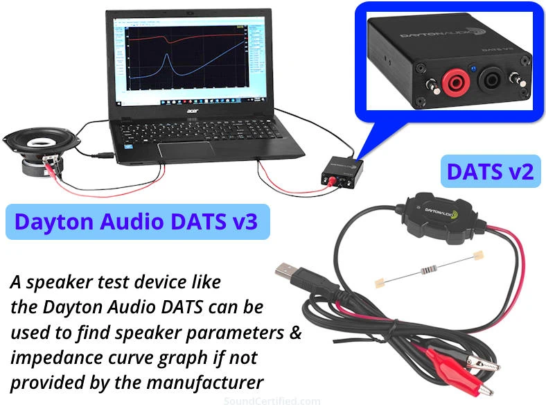
Option 1: Take measurements yourself
As I mentioned above, if you can’t find parameters (Thiele/Small parameters, such as the inductance Le and resonant frequency) for your speakers you can use a tool like the Dayton Audio DATS measurement system. By doing so you can measure several important speaker characteristics such as:
- Voice coil direct current resistance (DCR), or “Re.”
- Inductance (Le) as well as capacitance where needed.
- The entire impedance curve, in Ohms.
- Resonant frequency (Fs) and the peak Ohms value at that frequency.
Re can be measured by any resistance meter or multimeter with an Ohms measurement scale as well. While manufacturer specifications are generally accurate, it’s important to know that production changes can cause speakers to have specifications that don’t match what the documentation shows. Measuring them yourself can avoid unexpected disappointment and wasted time & money.
Option 2: Use example values from similar speakers
If you’re still unable to use (or decide against using) a test device to find the speaker parameters, you can get a relatively close result with my calculator by using example values from a speaker of a similar size and impedance.
While the result will be off a bit, the preset values I’ve provided are fairly typical for speakers of their type and will get the job done fairly well. Either way, using some type of Zobel network and/or series notch filter is far better than none at all!
Capacitor, inductor, and resistor component tolerances and price level
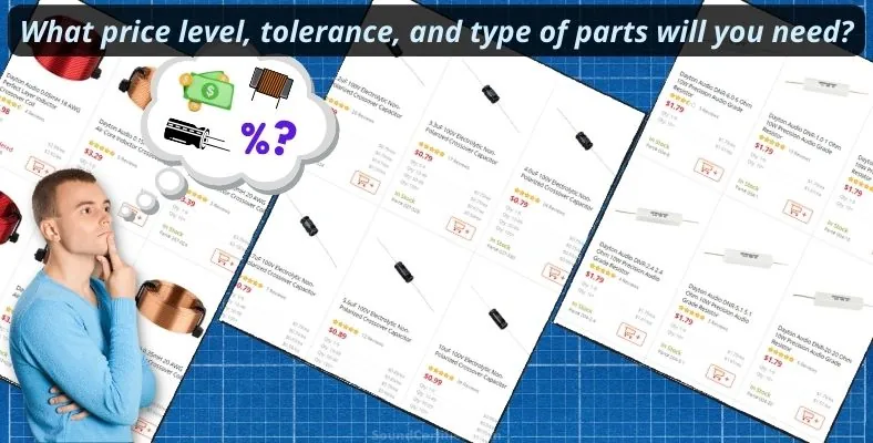
When preparing to build speaker impedance designs you can use standard quality parts. Higher-precision and more expensive parts aren’t necessary.
You do, however, need to follow a few basic component selection rules that also apply to other audio projects:
- Capacitors must be rated for at least the maximum amplifier output voltage at its rated max. power output. As a rule, however, it’s best to “overrate” them (choose a slightly higher rating) to avoid issues.
- Electrolytic bipolar capacitors will do fine. You can use other types for their longevity and (in some cases) a more compact size.
- Air-wound inductors are fine, although you may be able to find a better match for your needs when using iron core types.
- Inductors used in this situation can be of a smaller conductor size since they are not directing handling speaker current (unlike in passive speaker crossovers). 20AWG wire is fine.
How much does it cost to build DIY speaker impedance compensation?
Let’s use a real-world example. From my calculator above, for an 8Ω tweeter, we find need the following for each speaker:
- Zobel network: (1) 2.0µF capacitor, (1) 6.8Ω resistor.
- Series notch filter: (1) 36µF capacitor, (1) 0.9mH inductor.
Example parts cost table (Zobel network)
| Part/descript. | Price ($) |
|---|---|
| 2.2µF 100V bipolar electrolytic capacitor | 0.79 |
| 3Ω, 10W, wirewound resistor | 0.99 |
| 3.7Ω, 10W, wirewound resistor | 1.79 |
| Total: | $3.57 |
Example parts cost table (notch filter)
| Part/descript. | Price ($) |
|---|---|
| 33µF 100V bipolar elect. capacitor | 1.39 |
| 3.3µF 100V bipolar elect. capacitor | 0.79 |
| 1.0mH laminated iron core inductor | 5.79 |
| Total: | $7.97 |
Note that electronic components are sold in fixed standardized values, so we can use the next closest value available or combine additional parts to get the total value we need. A good example is using two resistors in series as they add.
Keeping costs down by picking a different crossover frequency
One way to keep costs down is by changing the crossover frequency to be at least two octaves above the speaker’s resonant frequency. An octave is a halving or doubling of a frequency.
Example: If the tweeter’s Fs = 834Hzz, two octaves would be 834 x 2 => 1,668 x 2 =3,336 Hz. Therefore, with a high-pass crossover frequency of at least 3,3kHz, we avoid the need for the series notch filter altogether.

Hi Marty – my tweeter manufacturer lists several Le values – which do I use for the calculator? The owner’s manual lists a value of .02mH. The technical datasheet lists an Le value of .3 @ 1000Hz and .04 @ 10,000Hz.
Also, if I’m not able to find an exact capacitor match and don’t wish to daisy-chain them due to space limitations do you recommend I go a little lower or higher than what is recommended? If I do the logic in my head I think if I put the capacitor a bit higher it might overly flatten the curve and if I put it a bit lower it will let it raise a bit but I don’t have the experience to know which usually results in better sound. My biggest complaint with the tweeter is it is a bit bright and harsh. I already installed an l-pad to attenuate it some but it is still a bit harsh sounding.
Hi Matt.
• Generally I use the 10kHz inductance specification since with tweeters we care about that upper range for our design(s). (You can test or calculate it yourself, and the 10kHz .04 value should be pretty accurate).
• Do you have a rough idea of how much of a difference in capacitance you are thinking about using? If it’s a relatively small difference, it should have a negligible impact on the tweeter.
• I would lean towards using a smaller value rather than larger value capacitor, only because the flattening will begin sooner, rather than later, in the frequency range (i.e., the frequency the compensation resistor comes into use will be lower).
Often I am able to get the (approximate) values I need by using a small second capacitor and I attach it to the primary/larger capacitor to keep size down. When connected in parallel, capacitors add in value (unlike inductors). Standard capacitors have often have a tolerance around 20% anyway, so they’re almost never **exact** values.
• How much did you drop your tweeter’s volume? It may need more. Some are fairly bright and need a larger dB reduction to get them under control.
Best regards!
Thank you Marty for the quick response, guidance and great site! I am upgrading the audio system in my convertible Mustang and it has been a learning experience for me – but fun!
I reduced the tweeters 6db and 4db but opted for 4db because the clarity was much better. When I’m driving with the top up and volume at reasonable levels the tweeters sound wonderful except that words with hard consonants can be harsh. When the top is down and the volume is up it is worse. The tweeters are Hertz DT 24.3 with the PEI surface and there are a lot of complaints about them being harsh but I bought them before I found your site. Resonance frequency for them is 2,800Hz and the crossover is at 3,500Hz (manufacturer xover – seems low). I have limited space to put an inductor so that is my concern with a notch but if I can put an inductor several feet away from the tweeter then it would work.
If I went with a smaller capacitor it wouldn’t be much – 2.2uF vs 2.4uF.
Take care,
Matt
Yes, often locating the crossover elsewhere makes things much easier, especially when space is tight. The same for a Zobel network or series notch filter. It won’t hurt to locate it away from the speaker(s).
Every time I built custom crossovers, there was simply no way to locate them near the speakers so I installed them in a good spot then ran wire to the speakers as needed.
If you were so inclined, you could switch between L-pad / resistor networks for the tweeters for either top-up or top-down use. That would be very simple to do with dual pole, dual throw (DPDT) switches or even a simple relay circuit and a single switch.
The 3.5KHz crossover point does seem a bit low, as often it’s at least one octave above the resonant frequency. But I would assume that was done for sales & marketing purposes, perhaps (?).
Best regards!
Thanks Marty for the great advice – you have been super helpful! The multiple L-Pad network sounds like a good idea! I’ll eventually get around to upgrading the amp and installing an aftermarket DSP but even then I think just flipping a switch sounds easier than opening the DSP app.
I had one last question – is there a way, or need, to calculate the resistor power ratings for a Zobel network and notch filter? It would seem both could short enough power across the network to approach the amp output but does that really happen in practice?
Thank you,
Matt