Want a great way to measure power for amplifiers, speakers, and much more? In this guide I’ll show you how to modify a Kill A Watt meter for low voltage and audio use.
Contents
Why modify a Kill A Watt meter?

The simple truth is that there are almost no affordable options if you’d like to measure audio power and voltage from an amplifier to a speaker. One option is the SMD Audio AMM-1 audio multimeter, which is really expensive at around $450!
Wouldn’t it be great to use a commonly sold – and affordable – energy use device like a Kill A Watt meter? Sure, but the problem is that when less than 50 to 60V AC is supplied, the internal power supply can’t power the internal electronics.
By modifying it for low voltage use, we can use it for a wide range of test voltages, audio power, and more, avoiding overpriced test instruments like the AMM-1.
The great news is that, as it turns out, the widely sold and popular P3 International Kill A Watt meter isn’t just a handy power meter for measuring alternating current (AC) energy usage in your home. They can also be modified to work like a more expensive test meter for less than $15-30!
To verify an amplifier’s rated wattage is as advertised, measure audio electrical parameters like power, voltage, and power factor, a meter like this can be a handy little test instrument and provide pretty good accuracy.
A few basics first

P3 International Kill-A-Watt power meters use the 120V AC supply to derive a small voltage to a chip on board integrated circuit (IC). This IC controls the LCD display and measures electricity energy use factors when an electrical appliance or other device is connected to its outlet on the front.
The meters run continuously, computing and displaying energy use data such as:
- Volts in standard root-mean-square (RMS)
- Current measurement in amps (A)
- Power consumption: kilowatt and wattage units, VA (apparent power energy consumption, based on the power factor, which can vary by the type of load connected), up to 1,875 Watts/VA.
- The power factor
- KiloWatt hour data over time
- Outlet AC voltage frequency, in Hertz
Understanding the 5V power supply used

A 5V direct current (DC) voltage is derived by rectifying the incoming AC power which supplies a common LM7805 voltage regulator as you can see above. We’ll need a way to ensure the 5V supply is active if we want to use it for voltages below 110V AC such as the output voltage of an amplifier to a speaker.
Why not just add a 5V power supply source?
I’m writing this article because, unfortunately, the idea for modifying a Kill A Watt EZ (model P4460) used in this Nuts and Volts magazine article isn’t an ideal solution, in my opinion – at least not for models other than the EZ (P4460).
In the article, a small 12V battery is connected to an additional LM7805 regulator and a diode at its 5V output side. Another diode is added to the ground terminal of the 7805 to attempt to compensate for the voltage lost across the output diode. The idea is to connect the ground terminal to ground through the diode, raising the voltage about 0.6-0.7V as compensation for the output.
The output voltage – approximately 5V – is then connected to the output pin of the original 7805 on the printed circuit board (PCB). In other words, it’s a secondary voltage source add-on.
However, when testing this approach, I ran into several major problems:
- The voltage supplied to the PCB from the add-on modification fell below 5V. It can’t fully compensate for the diode voltage loss as intended.
- Because the modification’s voltage falls just slightly around or below 5V, the Kill A Watt IC isn’t always able to start running consistently and may fail to start working.
- Battery current draw was higher than necessary – around 12mA versus a slightly lower amount when using the alternative I’ll provide here.
The meter’s IC needs almost exactly 5V to start, take measurements, and control the LCD display. If the voltage isn’t reliable, the display will be “stuck,” showing all display symbols and digits active, but nothing will happen afterward.
An alternative, then, is what I’ll show you how to do here: supply an external voltage before the existing LM7805 regulator so it can work based on the original design. We’ll need to ensure the power source under test by the meter cannot directly connect to our modified power source.
If a higher voltage is applied to a lower voltage source, there’s a possibility of it backfeeding and causing damage to an external power supply. Therefore, isolation is necessary.
DIAGRAM + steps: how to modify a Kill A Watt meter for low voltage use

You’ll need just a few steps to do the modification and a few tools as well:
- Small tip Philips head screwdriver
- Soldering iron and solder
- A sharp knife (X Acto style or retractable razor utility knife)
- Hand drill or electric drill + drill bit
- A small section of tape
- Strong glue or epoxy (for the 3.5mm jack option)
1. Accessing the circuit board

Open the plastic casing by removing the 3 screws from the rear. Once the case is open, the AC socket PCB can be pulled right out.

Remove the 4 small screws holding the circuit board in place. Carefully remove the circuit board and turn it around, revealing the 7805 regulator IC, circuit board traces, and so on. You may need to re-insert the rubber control buttons as they can fall out easily.
2. Modifying the board for low power use
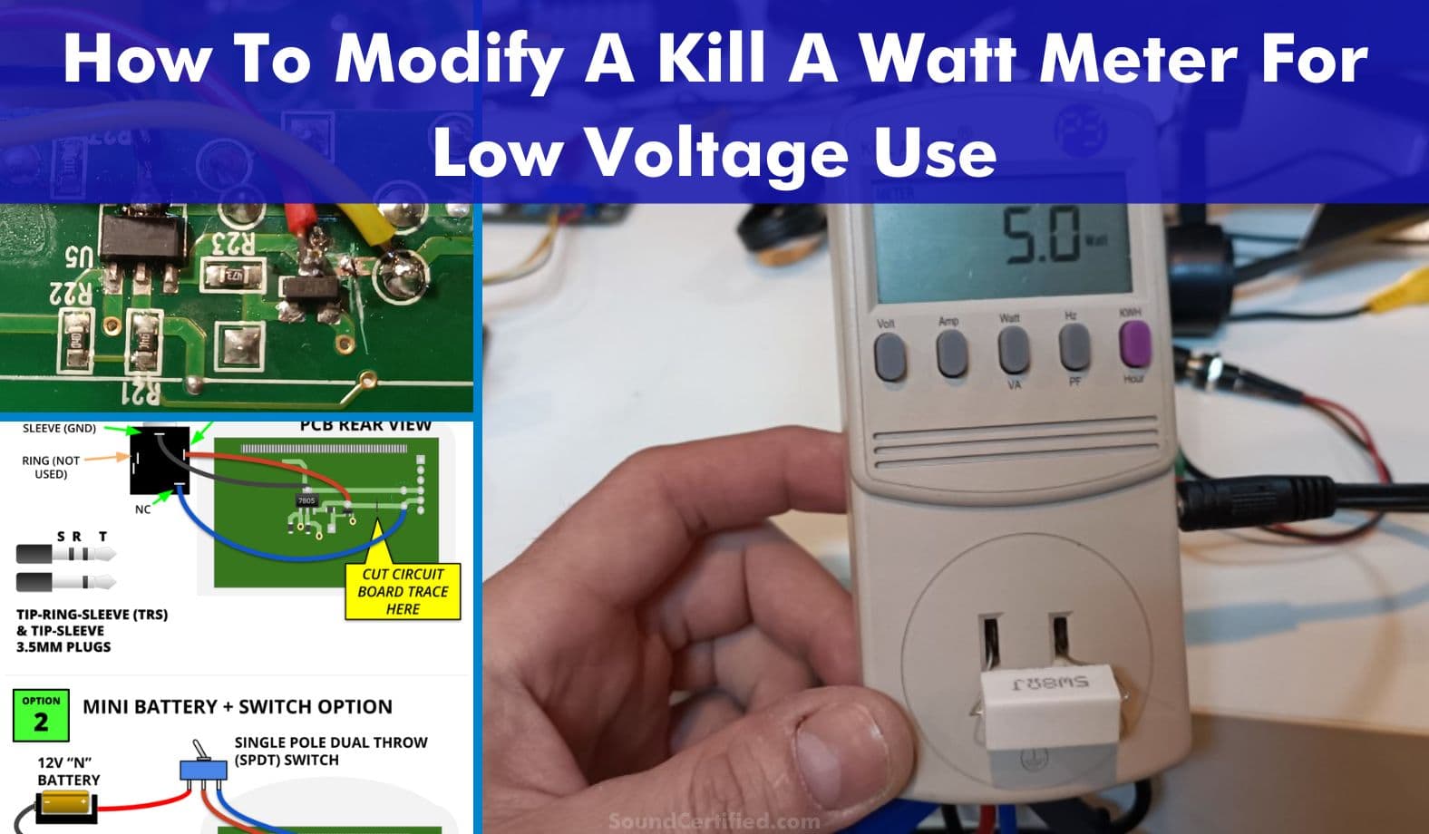
Depending on your needs, I’ve provided two options as you can see in the diagram above. In my specific case, I’ll be re-using a small 5V USB to 12V DC adapter and won’t need a battery to power the meter. I’m also using a 3.5mm (1/8 inch) stereo jack with normally closed (NC) pins available so it can work normally when not being used for low voltage.

Cutting the PCB regulator voltage trace

Find the circuit board trace as shown in the picture, and using a very sharp knife, cut across the circuit board trace until it appears to be separated. It may take multiple tries and a little bit of force.
Once you think it’s cut, double-check that there is no conductivity between the pin on the trace and the adjacent transistor. If there’s still a completed circuit, continue cutting until it’s correct.
Adding power wiring and retaining 120V use

Following the diagram provided, add the switch or 3.5mm – as needed – to the PCB with small wire of a few inches in length. I recommend about 4 to 5 inches to allow for ease of putting everything back together.
The 7805’s largest pin (located at the top) provides easy access to the ground path. Connect the secondary power (battery or external DC) wire anywhere near the trace around the transistor or 7805, although I recommend the top pin of the transistor.
Also connect the original DC supply wire to the trace section before the cut. The capacitor pin solder pad, located near the solder points for the ribbon cable, is a good location for this.
With a single pole dual throw (SPDT) switch or 3.5mm jack with normally closed (NC) contacts used as shown, when switched to normal use the meter will work normally for 120V. The 3.5mm jacks like those shown provide NC contact pins which each provide a closed circuit to the tip and ring conductors.
When a 3.5mm plug, either mono or stereo is used, the circuit will supply the provide outside voltage and the 5V regulator works normally but can measure lower voltages and power. With a 3.5mm removed, the contacts provide a connection to the original power source and the meter works normally.
3. Mounting the switch or jack

Using a drill, create a hole in the side as shown in the example here. Fortunately the plastic is fairly easy to drill through so this shouldn’t take very long. Widen the hole with a larger Philips head screwdriver, one side of a needle nose pliers tip, or something similar.
Once the hole is large enough, mount the switch or jack. A typical mini toggle switch shouldn’t need to be glued in place if a screw type collar mount is used. However, unfortunately a typical 3.5mm jack has a shaft that’s too short to allow panel mounting with a screw collar.

I had to apply a bit of epoxy to both sides to hold the jack in place. After allowing it time to harden the case can be reassembled. If you’re using a battery and socket, some double sided tape can allow to mount it to the case inside.
4. Putting everything back together

Carefully route the wires below the circuit board and re-insert the PCB in place along with its 4 screws. To avoid problems, you can add some type of tape over the switch or jack’s exposed terminals to prevent accidental short circuits.
Re-insert the AC board, re-install the case and screws. Test the unit first to verify it turns on using the switch or a 3.5mm plug with a connection to 9V or higher.

If there’s no problem, you’ll need to connect a voltage/power source and a load such as a resistor or speaker. Note that when measuring power or voltage, you’ll need to provide a sine wave test signal.
Both this unit and the more expensive AMM-1 multimeter don’t measure musical power in real-time. They need a since wave test tone to work properly
Connecting to a power source and load

I’m sure there are other options (for example, perhaps using .25″ spade crimp terminals) but to get a secure fit that won’t move, I used male and female electrical plugs with screw terminals and wire. A wire terminal connected to the load (outlet socket) side makes connecting more wiring easy.
Battery power draw
If you’re using a battery, there’s some great news: I measured only 7 milliAmps draw with the modification. The battery should be able to provide a fairly good life at that rate, unlike the alternative 5V modification I mentioned in the Nuts ‘N Volts article.
How accurate is the Kill A Watt meter?

As someone else said elsewhere, based on what I’ve seen, I cannot agree that the Kill A Watt meters meet the 0.2% accuracy you see listed above for the EZ model. However, when tested to verify measurement accuracy for voltage and power, the meter appears to have 1% and better accuracy for 3 digit readings.
For 2-digit range measurements, the meter seems to have a reading that’s off by about 100mV or .1 watts. Note that the internal components will have a voltage drop around 50-100mV I believe when measuring the outgoing versus source voltage.
Measuring power over 10-20W shouldn’t be much of an issue, especially for even higher power ranges. Bear in mind the device was designed for 110-120V loads so there’s a bit of a compromise you’ll have to live with when using it for low voltages or power ranges.

That being said, as you can see here, I validated the power of an 8 Ohm load resistor with about 6.32V applied from an amplifier for 5 watts. The reading was only slightly off occasionally, at about .1W when it happened. Similarly, I was able to measure as little as about 1W (2.86V volts RMS applied) to the resistor with a reading of about 0.9W shown.
To compensate for the internal loss (say around 0.05 volts) I was able to get an exact 1W reading.
Frequency limitations (good news!)
When testing the unit with a variable test tone, I verified the following:
- The KillAWatt meter seems able to provide reliable voltage and power measurements up to 600 Hertz. After that, the reading is somewhat off (about 0.2V, for example) and becomes mostly unusable after 800Hz.
- The frequency reading feature, however, can only report frequencies up to about 250Hz. The reading looks pretty unreliable after that.
This is great! I see you wrote it can measure reliable up to 600hz, what about low end ? 20, 15, 10hz?
Hi John I’ve verified the low end range. It appears to work ok down to around 15-20Hz.
That’s a great question. Thanks!