Speakers a little bit of a curious thing: they’re called 4 or 8 ohm impedance and so on, but most don’t actually measure that amount of resistance in Ohms when you check them!
Why is that, and what should you measure when checking the DC resistance for most speaker impedances ( 2, 4, and 8 ohm)?
I’ll explain everything in detail and provide a handy chart of some DC measurements you can expect.

Contents
What will a 2, 4, or 8 Ohm impedance speaker measure for DC resistance?
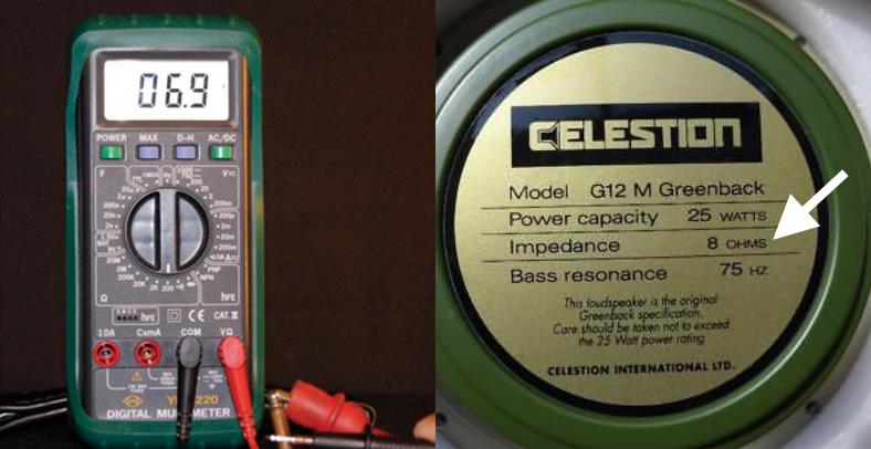
In the real world an 8 ohm speaker will have a resistance measurement less than its 8 ohm rating. That’s normal and is because the DC resistance and the total resistance, called the impedance, are not the same. DC resistance is always less than the total speaker impedance as you’ll see later.
You can find the typical DC Ohms measurement range for many common speaker impedances here. To use this chart, just find the impedance rating you’re interested in (1st column) and look at the Ohms measurement range in the 2nd column.
Speaker impedance DC resistance/Ohms range chart
| Speaker impedance | DC resistance |
|---|---|
| 2 ohms | 1.2-2 ohms |
| 4 ohm | 3.1-4.0 ohms |
| 8 ohm | 5.7-8 ohms |
| 6 ohms | 4.0-6 ohms |
| 1 ohm* | 0.5-1.0 ohms |
| 16 ohms* | 12-16 ohms |
*(1 ohm speakers are unusual but can be found in some car stereo products such as Bose premium amplified systems. 16 ohm speakers may sometimes be used for home or other speaker systems but you won’t run across them very often, either.)
What is speaker impedance? Impedance vs resistance explained
A speaker’s impedance is the total resistance to the flow of electrical current when it’s connected to an amplifier or stereo. It’s a combination of the direct current (DC) resistance AND the portion of resistance due to magnetic fields created when an alternating current (AC) musical signal is applied.
Both resistance and impedance are measured in Ohms so the end result is a total value in Ohms also.
For example, when measuring a speaker’s resistance with a test meter or Ohm meter, the meter puts out DC voltage and measures DC resistance. If you had some fancier test equipment and a lab to put out an AC signal, you’d also see that a speaker develops more resistance based on the frequency applied to it.
Speaker impedance vs resistance explained
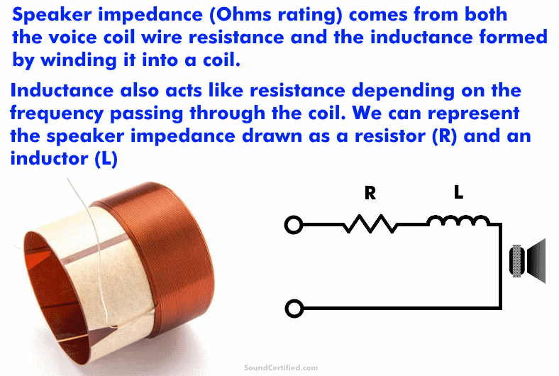
As I mentioned, speakers use a voice coil that’s a long length of wire spun into a tightly wound coil by high-precision machines at the speaker factory.
When you play music and drive a speaker with power, magnetic fields are created as current flows through the coil. These fields create an opposition (resistance, called reactance in this case) to the current flowing through it. This is a very common property of wire coils and is also used to create electric motors, spark plug coils for engines, stun guns, and much more.
The coil has a property called inductance that affects how strong the magnetic fields are. Inductive reactance is different from resistance as it changes as the frequency changes, unlike DC resistance.
This kind of “resistance” is called inductive reactance.
Where the total speaker impedance comes from
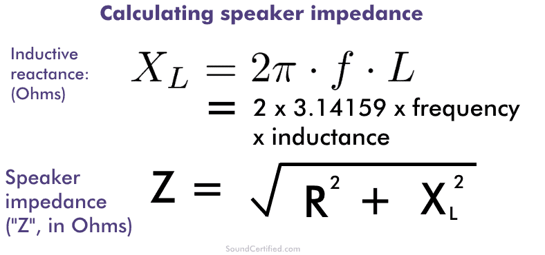
The mathematical formulas for calculating speaker voice coil inductive reactance at a given frequency and total speaker impedance. It’s a bit complicated, but not too bad once you understand it!
Unfortunately, impedance/inductive reactance is a bit complicated to deal with mathematically. Because of how inductance works and the physics involved, the total speaker impedance (resistance + inductive reactance) isn’t as simple as just adding together the resistance and the inductive reactance.
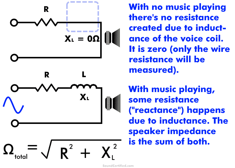
Instead, speaker impedance is found from the square root of the sum of the squares of the coil’s wire resistance and the inductive reactance.
Inductive reactance is represented as “Xl”, pronounced “X sub L” and is measured in Ohms just like resistance. Inductance is measured using a unit called the “Henrie” and is shown as an “H.” “uH” means microHenries (1/100,000 of a Henrie), mH” represents milliHendries (1/1,000) of a Henrie), and so on.
Inductors are extremely useful for audio – especially for speaker crossovers. In that case, they’re a critical component for high- or low-pass crossovers and are chosen based on their inductance.
How to measure speaker impedance with a test meter correctly
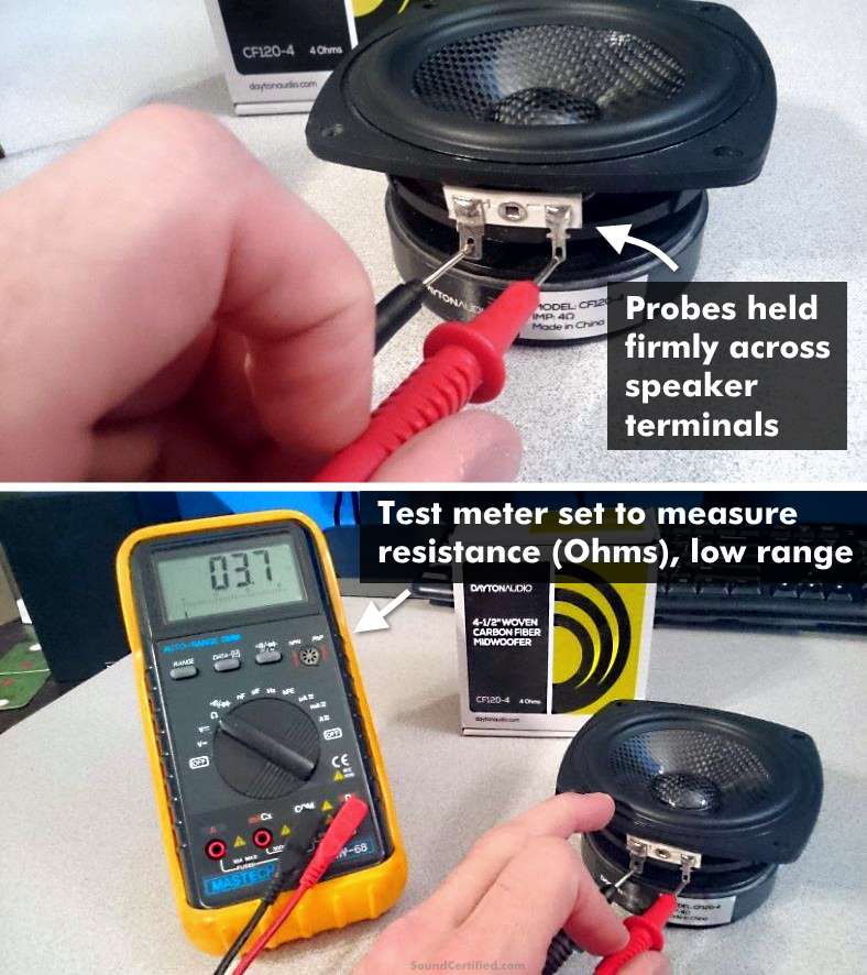
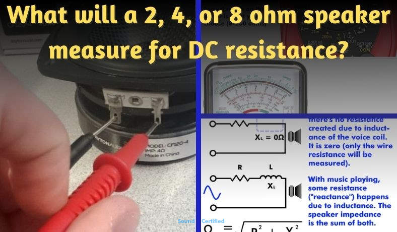
In this picture, you can see an example of how to measure speaker impedance using an Ohm meter or any standard test meter set to measure resistance in Ohms. To do so, set it to one of the lowest ranges (0-10 Ohms, 0-20 Ohms, etc) or the auto-range setting if available. Touch the test probe leads firmly against clean, bare metal on the speaker terminals with at least one speaker wire removed to avoid a false measurement.
To measure the impedance of a speaker you’ll need a multimeter or a dedicated resistance meter.
Do the following:
- Switch on the meter and set it to measure Ohms on the lowest range. This is often the x1 range, 0-10 Ohms, 0-20 Ohms, or auto-range setting.
- IMPORTANT!Disconnect one or both speaker wires from the speaker to avoid a false reading due to other resistance that may be connected to it. If other things are connected they can cause false readings and give you the wrong idea.
- Hold the probes firmly against the speaker terminals on a clean, bare metal spot. The meter should quickly settle to a reading. The meter will show the DC resistance of the voice coil wire.
- Use the measured value to determine the closest approximate speaker impedance (see my chart above if you like)
- For speakers inside a cabinet or enclosure such 2-way speakers, crossovers may be in use and these can interfere with this reading with a few exceptions. However, in many cases, you still measure the resistance of a woofer fairly well. (I still recommend disconnecting at least one wire before taking a measurement.)
Remember that you won’t measure exactly 4 ohms for a 4 ohm speaker or 8 ohms for an 8 ohm speaker, for example. The DC measurement is almost always 30% lower than the impedance rating on the speaker’s package or label.
Selecting the correct test meter resistance (Ohm) range for speakers
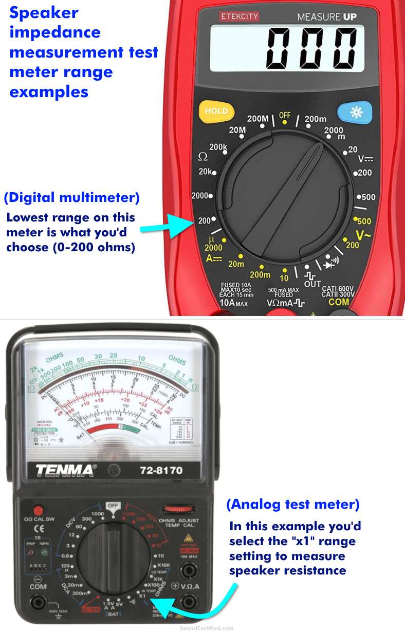
It’s important to use the correct Ohms range on your meter when measuring speaker impedance. That’s because the wrong setting may display nothing useful or mistakenly give you the idea that the speaker is blown or even an incorrect reading.
If you’re not sure, check the test meter’s manual. Many modern digital meters often have an auto setting that will automatically adjust for the Ohm measurement it detects and will change the range and decimal place automatically for you. Other meters require you to select the correct range manually.
As a general rule, use the lowest range that includes 0-10 ohms (or similar) then go up if necessary.
That should almost never happen, but in the case of a poor connection, a blown (or almost blown) speaker, stuff can happen and you could get a reading that’s not really the speaker’s normal DC resistance.
In my experience, however, that’s not something you’ll run across often, if at all.
What happens if my speaker impedance is too low or too high?
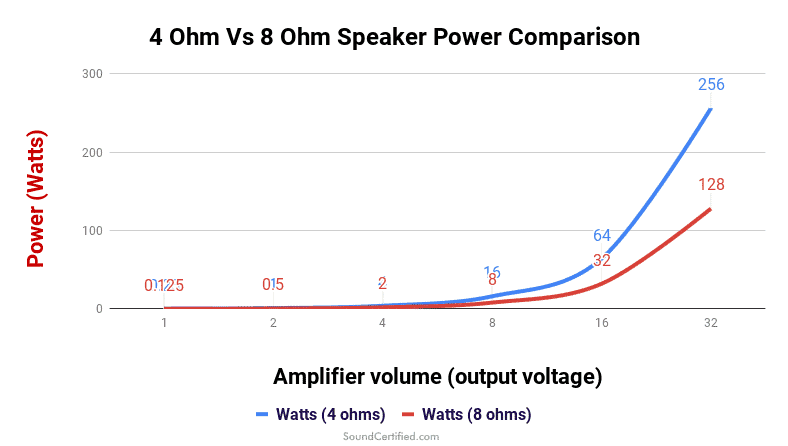
This is a graph showing how a higher impedance speaker makes less power than the correct speaker that should match an amp or stereo. For example, using an 8 ohm speaker in the place of a 4 ohm one means you’ll get 1/2 the power and as a result, you’ll never be able to the same volume or performance that you paid for with your system.
Using a speaker that’s not matched to the stereo or amplifier it’s rated for can have relatively minor – or even terrible results depending on what you’re dealing with:
- Using a higher impedance speaker won’t damage equipment. The result will be lower power developed and therefore lower possible volume. You may also introduce problems with speaker crossovers, however.
- Using a lower than specified impedance speaker will cause radios or amps to suffer extreme heat and even permanent damage because the current output will be much more than what it’s designed for.
As an example, if you were to use 8 ohm speakers in the place of 4 ohm car stereo speakers you wouldn’t hurt anything because less current will be output and it wouldn’t overheat. The problem will be (although it will play fine, otherwise) is that the total power available will be 1/2 that of a 4 ohm speaker.
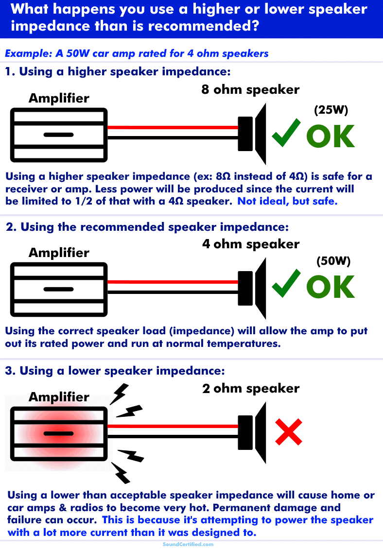
However, there’s a huge problem if you use a lower impedance speaker that’s matched to the amp, home stereo, or etc. The end result will be that it’ll being to overheat and can potentially suffer permanent damage and stop producing sound.
That’s because using a lower speaker impedance causes the radio or amp to attempt to put out twice as much (or more!) current than it’s designed for.
If you’re lucky the radio, home stereo, or amplifier will shut off to protect itself. Unfortunately over the years more often than not I’ve seen amps or radios burn out their output stages because of a short-circuit or the wrong impedance speakers being connected.
Why do lower impedance speakers cause an amp or radio to burn out?
The high-power transistors used in home or car audio devices can only handle a certain amount of electrical current (amps) or heat. When forced to handle more than their safe limit they become incredibly hot and start to break down. Before long they’ll stop working altogether as the semiconductor components are destroyed.
What happens if I use a different impedance speaker on a crossover?
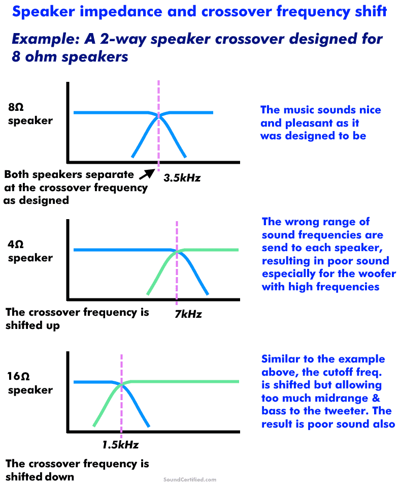
Diagram showing what happens when you change the speaker Ohm load connected to a crossover: crossover shift occurs. This means because it was designed for a different speaker impedance, the frequency at which it works changes.
As I mentioned earlier, speaker crossovers are based on parts (capacitors and inductors) that work as filters according to the speaker load they’re connected to. Because of this, when you change the speaker impedance you change the crossover frequency and the sound.
You may notice several problems after doing this:
- A “harsh” sound from woofers or midrange speakers. Tweeters may sound distorted and being to “break up” the sound at volume.
- A “thin”, weak quality to the music.
- Gaps in the sound ranges you should be hearing.
Speaker crossovers can only be used with the speaker impedance they’re designed for or they won’t sound the same.
For example, using an 8 Ohm home speaker crossover with a 4 Ohm car speaker won’t work correctly. That’s because the part values were chosen for one impedance only. When you change that, it dramatically changes the crossover frequency!