Crossovers are extremely important to speaker systems and a big reason we’re able to get sound quality we love.
On the other hand, things like the crossover frequency (Fc), slopes (db per octave, and how it all works can be a little bit complicated if you don’t understand how it all works. I’d love to help!
In this article I’ll explain:
- What the crossover frequency Fc is and why it’s important
- What a crossover slope is and the most common you’ll come across
- How to calculate dB crossover drop for frequencies including Fc
- The role of inductors and capacitors (and “reactance” for Fc)
Contents
Crossover frequency Fc and crossover slopes explained
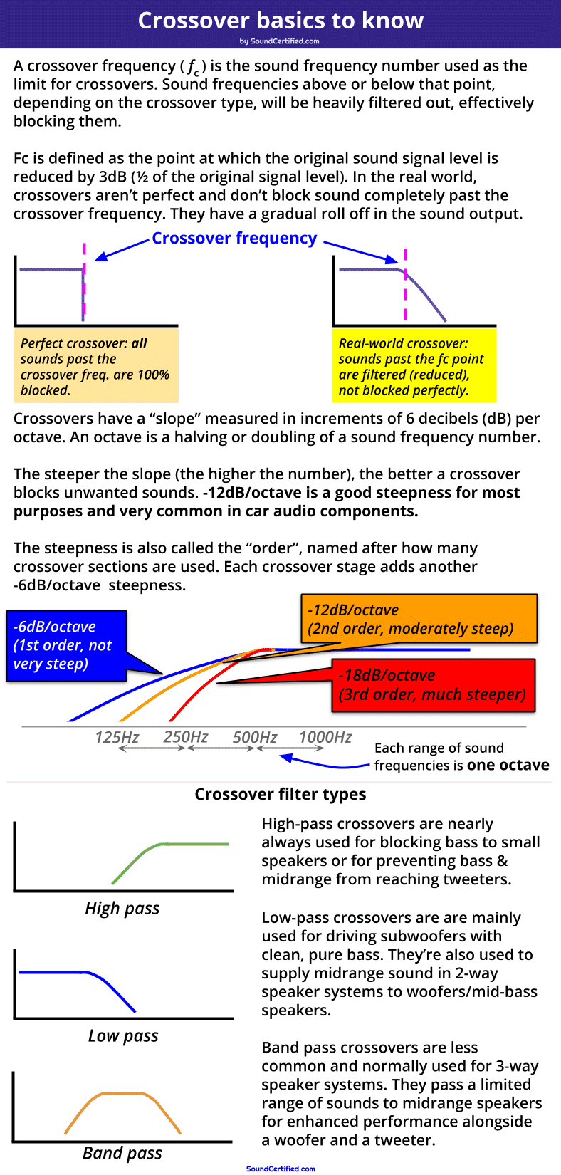
This diagram shows examples of the 3 main filter types used in crossovers. Also shown are the most common crossover slopes which is the “steepness” of the filter (how effectively they block frequencies beyond the crossover frequency).
A crossover frequency, commonly written as Fc, is the audio frequency point in Hertz (Hz) at which the crossover delivers -3dB (1/2) power output to the speaker. Fc is the marking point after which sound frequencies will be greatly reduced to prevent them from reaching a speaker.
Past the crossover frequency (Fc) point the power output by the crossover will drop more and more, with less and less power sent to the speaker. As it so happens, at Fc the voltage output to the load (speaker) is 0.707 x the input voltage meaning you can calculate the decibel drop based on the voltage out versus the voltage in.
Why crossover frequencies are important
When designing speaker crossovers, the crossover frequency (fc) is used as a sort of line that marks where we want to start blocking the sound frequencies sent to a speaker. It’s usually based on the specifications provided by a speaker manufacturer that lists the sound frequencies a speaker can produce with good sound response and without distortion.
For example, tweeters can’t play bass notes from music and can even be damaged by them. Knowing that, we’d want to choose a crossover frequency high enough to block bass notes sent to tweeters to prevent distortion or damage. (Typically tweeters have crossover frequency in the thousands of Hertz [written as KiloHertz or kHz for short] like 3.5kHz, 5kHz, and so on – well above the range of bass & midrange sounds in music).
A crossover frequency is also sometimes called the corner frequency or cutoff frequency since we think in terms of how sounds are “cut off” after that point.
The crossover frequency Fc is very important for crossover design
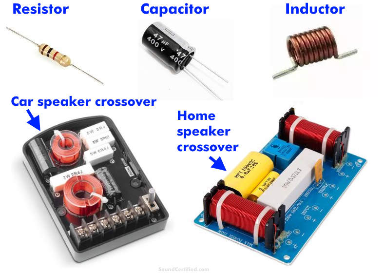
Speaker crossovers (also called “passive” as they don’t use electrical power to operate) use capacitors and inductors that are selected based on part values available and their cost. A crossover is designed based on a starting Fc frequency and adjusted as needed for the design goals.
Using the crossover frequency Fc as a starting point allows speaker system designers to calculate the part values needed (capacitors and inductors) depending on the speaker impedance. Since you can’t buy parts in just any value, the Fc we get based on what we want is a good starting point we can work with and adjust as needed to work with parts based on availability, price, and other factors.
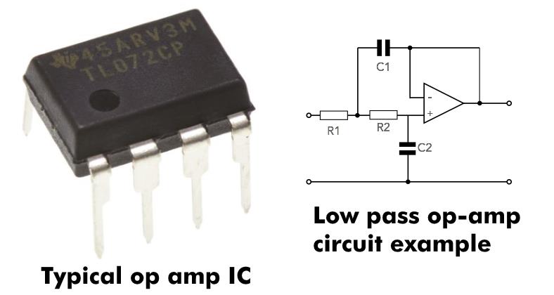
Operational amplifiers, also called op-amps, are the most important building block for electronic crossovers. Electronic crossovers perform exactly the same job (and have the same basic behavior) as passive (speaker) crossovers. The difference is that they work on low-level signals before they’re amplified while passive crossovers work with amplified signals after the amp output.
Just like their larger passive capacitor or inductor-based counterparts, operational amplifier based crossovers have the same slopes and crossover frequency behavior. They simply do it with the signal before it’s amplified instead of after it.
How to calculate decibels (dB) for the crossover frequency Fc
All sound frequencies after the crossover frequency are cut more and more past it with an increasingly steep reduction – to the point where they’re almost completely blocked.
In other words, a crossover filters out a range of sounds you’d like to prevent reaching speakers, starting at the crossover frequency.
In the electrical engineering world, we traditionally use decibels (dB) when we talk about power measurements since they’re often non-linear. This just means that mathematically, power is often measured, charted, and tracked using exponential math such as logarithms (“10 to the power of x”, for example).
Because crossovers reduce power at their output, it’s pretty common to measure the output reduction in decibels. One reason for this is that they have a gentle “slope” (downward curve) rather than a straight line if you were to see them graphed across the full range of audio frequencies.
For that and other reasons, we can measure the power output reduction in dB. To do so, you’ll need to know either (1) the power before and after the speaker/from the amp, or (2) the voltage at the speaker and from the amp.
Knowing those, you can easily calculate the dB output of a crossover with a scientific calculator on your computer or smartphone.
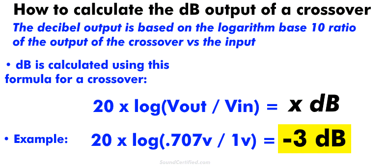
You can calculate dB for a crossover using these formulas:
- For voltage: 20 x log(Vout / Vin ) = x dB
- For power: 10 x log (Power_out / Power_in) = x dB
Understanding crossover signal level in vs out and “negative gain”
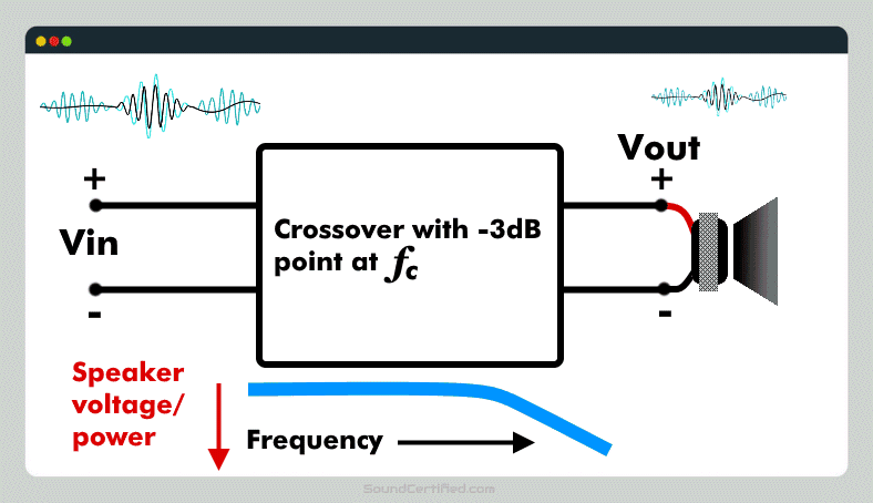
Crossover voltage out (called here “Vout”, the voltage to a speaker delivered from a crossover) can never be higher than the input – that’s not possible. Crossovers can only reduce the input directed to a speaker – they can’t amplify it. Some electronic crossovers do, but those intentionally have a gain on purpose and that’s not common in most cases.
For that reason, you’ll always get a negative dB answer if you do the math for the output of a crossover.
For the record, a negative dB value is used to show a reduction in engineering math while positive usually means a gain or increase in a signal. Amplifiers have a positive dB output (gain) while crossovers and some other components like resistors have a negative gain (a negative dB effect on a signal).
Attenuation is another way of describing a negative gain.
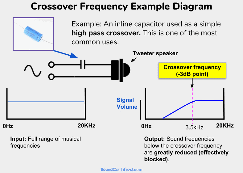
How a crossover frequency Fc works: example diagram
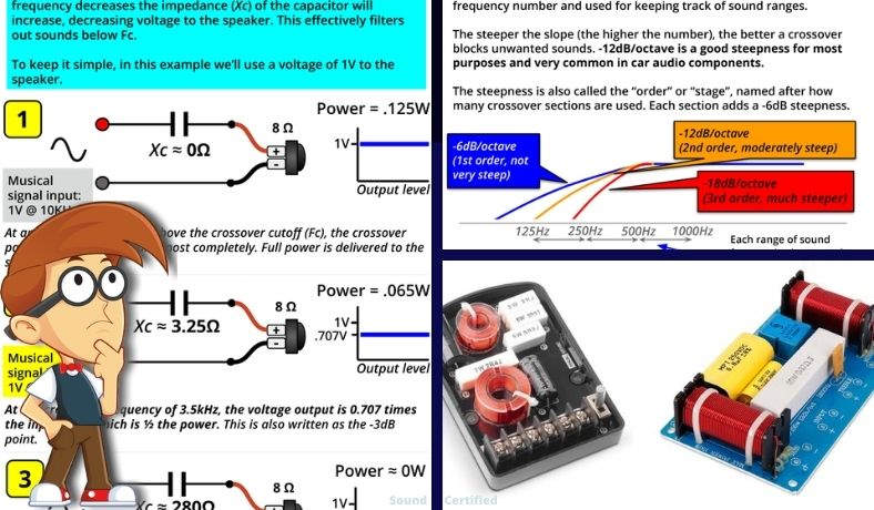
An example of a very common and simple high-pass crossover. A capacitor in series with a speaker will allow higher frequencies (above Fc) to pass with almost no volume or power drop to the speaker. It acts as a zero Ohm resistor (a short circuit wire) in series with it. However, for audio frequencies below Fc, the “resistance” (impedance, called capacitive reactance) of the capacitor will increase, allowing less and less voltage & power to reach the speaker. It will act like a very high-value resistor in series and therefore will block most of the signal from an amp sent to the speaker. In other words, a high-pass filter!
One of the problems I’ve found when we’re talking about this topic is picturing it in your mind. For example, it can be hard to understand what actually happens in real life when actually playing music in the real world vs just some explanation you’ve found on the internet.
All crossovers work the same – understand one, you understand them all (well, mostly!)
One important note I need to make is that the principles are the same regardless of the number of “orders”, or stages, a crossover has. For example, a simple 1st order crossover with a capacitor connected inline with a tweeter works on exactly the same principle as a fancier 2nd order 2-way crossover.
It’s just that the details are a little bit more complicated – not how it works. That part never changes.
There are some crossovers with more sophisticated features & designs I won’t get into here, but for the most part, the majority are all the same and do the same thing to varying degrees. The great thing is that once you understand the basics very well, you’ve got it figured out for the most part!
The fundamentals of how crossovers work with Fc

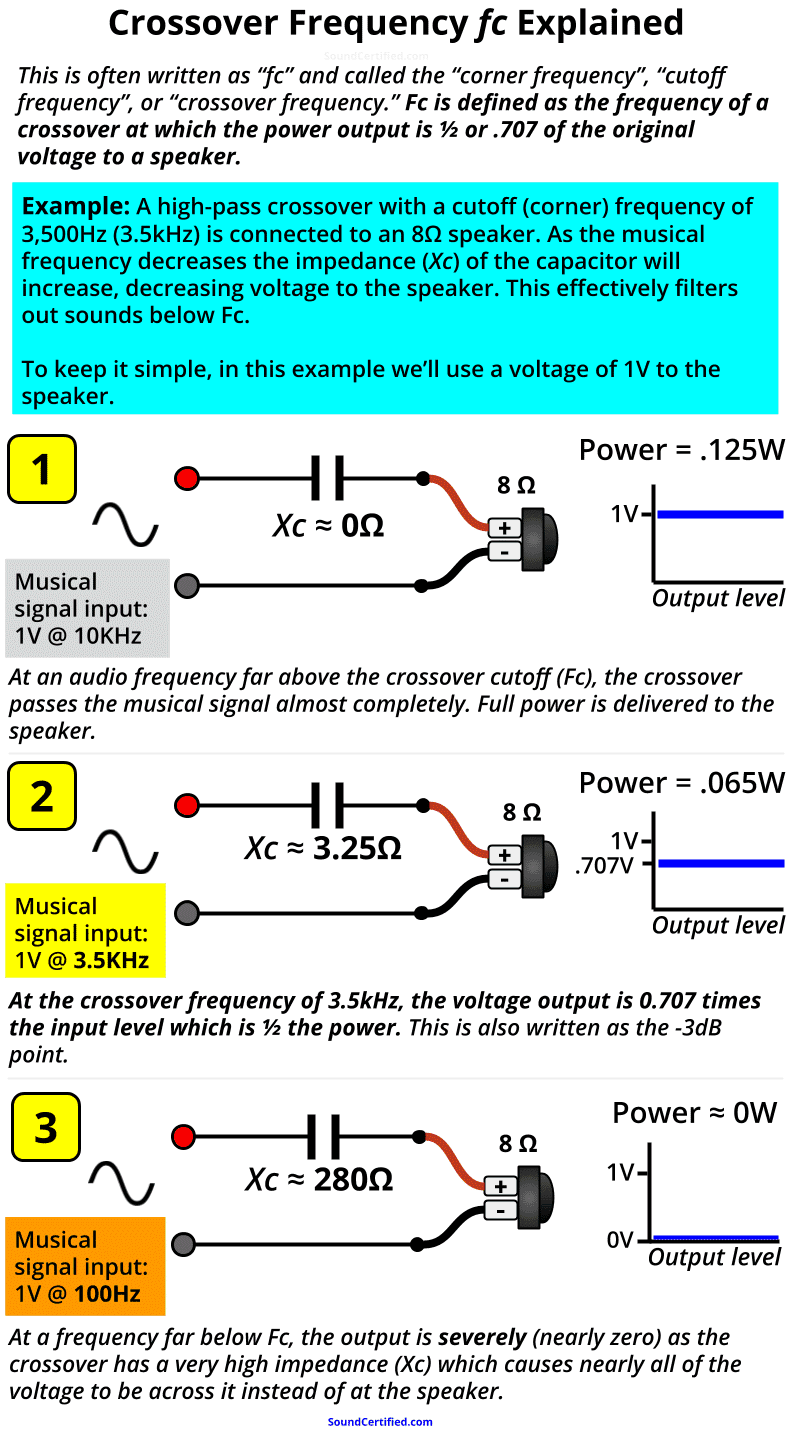
The most important thing to know is that crossovers work by “absorbing”, or preventing, voltage and power from going to the speakers they’re connected to for the sound frequencies we don’t want them to play.
In the example from my diagram further above, you can see that:
- Above the cutoff frequency Fc, a capacitor acts like an almost zero resistance connection – nothing is blocked and it acts almost like a straight section of wire.
- When audio frequencies begin to reach Fc, the impedance of the crossover goes up, acting like a high-value resistor in series with the speaker. At Fc, the speaker receives only 1/2 the power it would otherwise (which also happens to be .707 times the input voltage from the amp or stereo).
- The farther we go past the Fc limit, the crossover’s impedance is much bigger in Ohms; in fact, past a certain point, it will be several hundred Ohms typically. When that happens the speaker has about 0v and no power to it.
As you can see elsewhere in my article, the “steepness” of the drop in the power & signal level to the speaker depends on the crossover slope. A crossover’s slope is basically just a result of how many “stages”, or crossover sections, are used as needed for the particular speaker system or speakers we’re working with.
Crossovers like you see here and are always in increments of 6 decibels (dB) Per Octave:
- 1st order crossover: a single capacitor or inductor is used, -6dB per octave reduction (not very steep).
- 2nd order crossover: Two components sections are used: one capacitor, one inductor. –12dB/octave reduction (steeper, more effective, very popular).
- 3rd order: two capacitors + 1 inductor or 2 inductors + 1 capacitor are used: –18dB/octave cutoff.
..and so on, with -12db being one of the most common crossover slopes you’ll find for both car audio crossovers and home audio speakers too.
Crossover frequency formula math: inductive and capacitive reactance explained
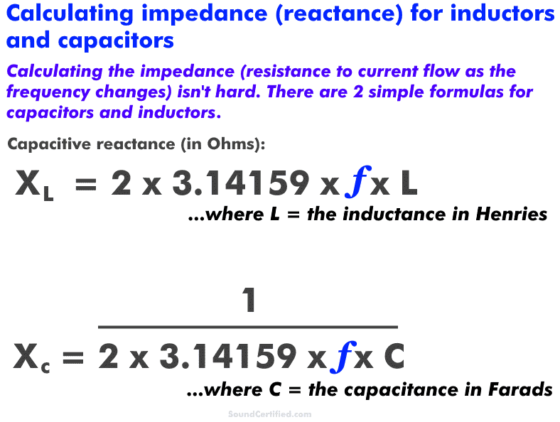
Shown here are the basic formulas for simple 1st order crossovers using capacitors and inductors. Capacitors have an impedance (Ohms) value that depends on the frequency just like inductors do.
Capacitors and inductors have a “resistance” called reactance (in Ohms just like resistance) that depends on the frequency. Here are a few basic things to understand:
- Capacitive reactance increases as the frequency DECREASES. It’s normally written as “Xc.” Capacitance is marked in units of Farads, with most capacitors being values in the microFarad (uF) range, nanoFarad (nF), or even picoFarad (pF).
- Inductive reactance INCREASES as the frequency increases. It’s normally written as “Xl.” Inductance is marked in units of Henries and typically found in units of microHenries (uH) or milliHenries (mH).
Again, it both cases, it’s just a form of impedance much like how a speaker voice coil that has a certain amount of inductance due to the coil of wire inside does. Both are measured in Ohms (Ω).
However, they complement each other and behave pretty much like the opposite of each other. For example:
- Capacitors act like high-pass filters when connected in series and low pass filters in parallel.
- Inductors act like low-pass filters when connected in series and high-pass-filters in parallel.
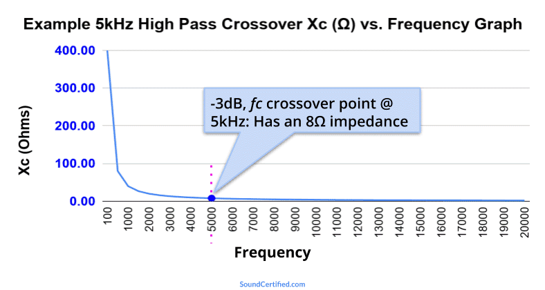
This graph shows an example of a simple high pass capacitor using a 3.98 microFarad capacitor with an 8Ω speaker with a crossover frequency (Fc) of 5kHz. At the Fc value, the impedance is the same as the speaker load (8Ω) which means the speaker power has dropped to 1/2. Further below Fc the impedance grows higher and higher, blocking bass frequencies more and more.