Have you ever wondered what really happens if you use a different impedance speaker with a speaker crossover? It’s a great question!
As it turns out, the speaker impedance (Ohms) does make a difference in how a speaker crossover works and affects the sound. I’ll explain it all in detail in a way that anyone can understand.

Contents
What is a speaker crossover? What does a crossover do?
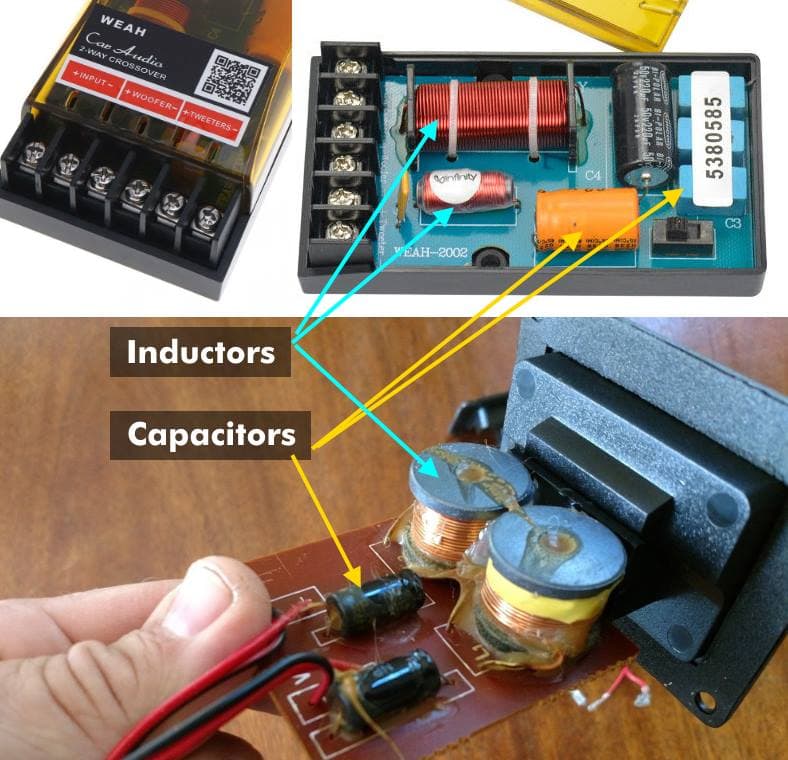
Top: A typical car stereo speaker crossover, with the main parts labeled. Bottom: A typical home stereo speaker crossover, which is extremely similar. (These are normally installed inside the speaker cabinet) Both use capacitors and inductors to form crossover filters and control the sound sent to tweeters, midrange speakers, or woofers for best audio sound quality.
Speaker crossovers are often called “passive” crossovers because they pass signals without need a power supply unlike electronic (“active”) crossovers. They work using passive components: capacitors and inductors.
A speaker crossover is an electrical circuit that uses inductors and capacitors to filter a speaker signal and split it among 1 or more outputs. The outputs depend upon the frequency response of the speakers used.
They’re different from electronic crossovers in that instead of being connected to the signal path (RCA cables, for example) speaker crossovers are connected to the output of amps or stereos. The speakers are then connected to the crossover’s speaker connections.
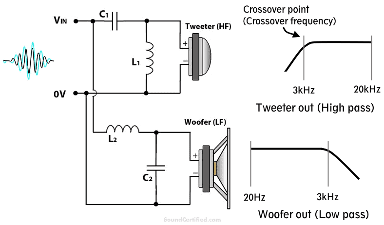
One of the most common speaker crossover types in use today: A 2nd-order 2-way speaker crossover with tweeter and midrange/woofer outputs. Inductors are represented with an “L” symbol and capacitors with a “C” symbol. Speaker crossovers work to separate the sound sent to certain speakers for improved sound, lower distortion, and to control over how speakers are used. For example, they block bass that tweeters can’t produce and highs that a woofer can’t produce well.
Inductors and capacitors have some really interesting (and really useful!) properties when an electrical audio signal flows through them:
- Inductors are coils of wire that have more resistance (called impedance, in this case) to a high-frequency signal than a lower one. Therefore they filter out higher sound frequencies when connected in series.
- Capacitors have more “resistance” to a low-frequency signal than a higher one when in series. The lower the frequency, the less signal that is allowed to pass.
When a capacitor or inductor has a signal applied to it past a certain frequency range called the crossover frequency, corner frequency, or cutoff frequency, the amount of signal it allows to pass is lowered, making it act like a filter.
This means the speaker will receive less and less of the speaker signal that we want to block, reducing the volume output for that unwanted range of sound. It’s important to understand that the frequency at which this happens depends on the speaker impedance (Ohms load) connected.
Speaker crossover orders (slopes) and designs
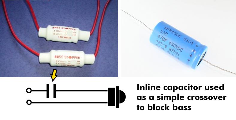 When used in series with a tweeter, a crossover filters out damaging and distorting bass that it can’t handle. When used alone, a single capacitor is a 1st order (single-stage) crossover with a slope of -6dB per octave – the most basic level.
Crossovers come in different designs for different types of audio tailoring & performance levels, but they all work in the same basic way. They’re designed with “orders”, or stages, which when added make their filtering even better at blocking unwanted sounds from reaching speakers.
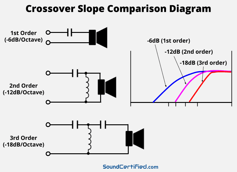
For example, here’s a list of common order crossovers you’ll often see:
- 1st order: Not very steep -16dB/octave), consists of a single capacitor or inductor in series with the speaker.
- 2nd order: Better -12dB/octave filtering, using TWO components for each speaker.
- 3rd order: Even better, with -18dB/octave filtering, using THREE components for each speaker.
Crossover filters are always multiples of 6 decibels (dB) because of how the components work. A “steeper” (higher) crossover order just means it’s more effective at blocking the range of sound frequencies we don’t want to reach the speaker.
What is speaker impedance? How does speaker impedance work?
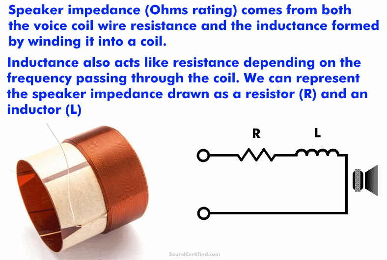
Speaker impedance is the total amount of resistance a speaker has due to both the resistance of its wire coil and the inductance of the wire coil loop. Impedance is rated in units of resistance called Ohms.
Just like you can’t have a short circuit across a battery, an amp or stereo needs some amount of speaker load impedance to limit how much electrical current the radio or amp tries to supply.
Unlike a straight wire that goes from one point to another when you hook up power, the voice coil’s wire winding forms a loop that has an electrical property called inductance. Inductance is a bit different from resistance as it changes as the frequency changes. It’s called inductive reactance.
For nearly all speakers, this means that the real impedance (the total resistance) actually changes somewhat as the music plays.
When we refer to the impedance of speakers, most of the time we’re referring to the category (general Ohms range) of the speaker used to match home or car stereo amplifiers.
How does speaker impedance work?
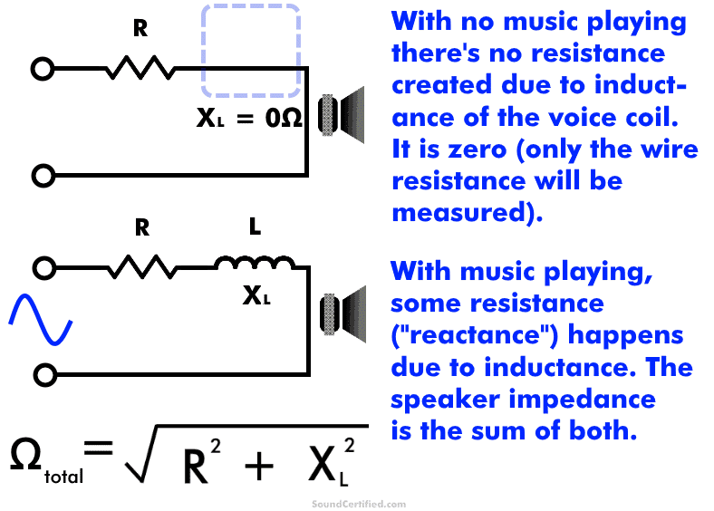
When a musical signal (made up of alternating current) drives a speaker it creates magnetic fields as electrical current flows through the tightly wound wire voice coil. What’s interesting is that a coil of wire develops magnetic fields around it that resist the flow of current when this happens.
That’s where the frequency-dependent part of a speaker’s impedance comes from.
(This also happens with other electrical devices too, like motors, engine spark plug coils, and more. They also deal with electrical resistance as alternating current (AC) is applied.)
What happens if I use a different impedance speaker on a crossover?
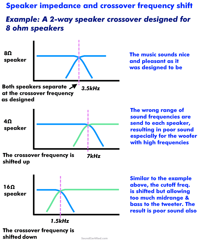
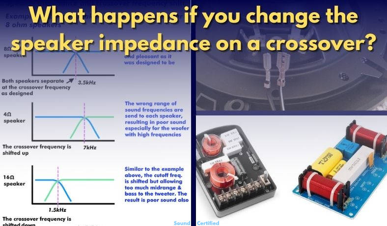
Diagram showing what happens when you change the speaker Ohm load connected to a crossover: crossover shift occurs. This means because it was designed for a different speaker impedance, the frequency at which it works changes.
Crossover shift when using different impedance speakers
As I mentioned earlier, speaker crossovers are based on parts (capacitors and inductors) that work as filters according to the speaker load they’re connected to. Because of this, when you change the speaker impedance you change the crossover frequency and the sound.
You may notice several problems after doing this:
- A “harsh” sound from woofers or midrange speakers. Tweeters may sound distorted and begin to “break up” at a lower volume than they used to.
- A “thin”, weak quality to the music.
- Gaps in the sound ranges you should be hearing.
Speaker crossovers can only be used with the speaker impedance they’re designed for or they won’t sound the same.
For example, using an 8 Ohm home speaker crossover with a 4 Ohm car speaker won’t work correctly. That’s because the part values were chosen for one impedance only. When you change that, it dramatically changes the crossover frequency!
What happens to a crossover when I half the speaker impedance?
When you change the speaker impedance connected to a speaker crossover it can significantly shift the crossover’s cutoff frequency. As a general rule:
- Halving the speaker impedance (ex.: 8ohms to 4 ohms) doubles the crossover frequency (Ex.: 3.5kHz goes to 7kHz)
- Doubling the speaker impedance (ex: 8 ohms to 16 ohms) halves the crossover frequency (Ex. 3.5kHz goes to 1.75kHz)
We don’t want that because it allows the speakers to be sent a sound range they’re not suited for and sounds bad. In the case of tweeters, bass & midrange are bad because they can’t produce it properly. In fact, after a certain power level tweeters can be damaged when driven hard by bass frequencies.
Similarly, many woofers can’t produce high frequency sounds well and can sound terrible.
Normally, if you change the speaker Ohms load you’ll have to replace the speaker crossover as well to match the Ohms load.
However, there is a workaround that offers some hope…
How can I use speakers with a different impedance? Is it possible?
The great news is that it is possible to use a different speaker impedance with a speaker crossover it’s not designed for! There are some compromises you’ll have to make, though.
How to match a different speaker impedance to a crossover
This is actually pretty simple! To match a speaker impedance to a crossover:
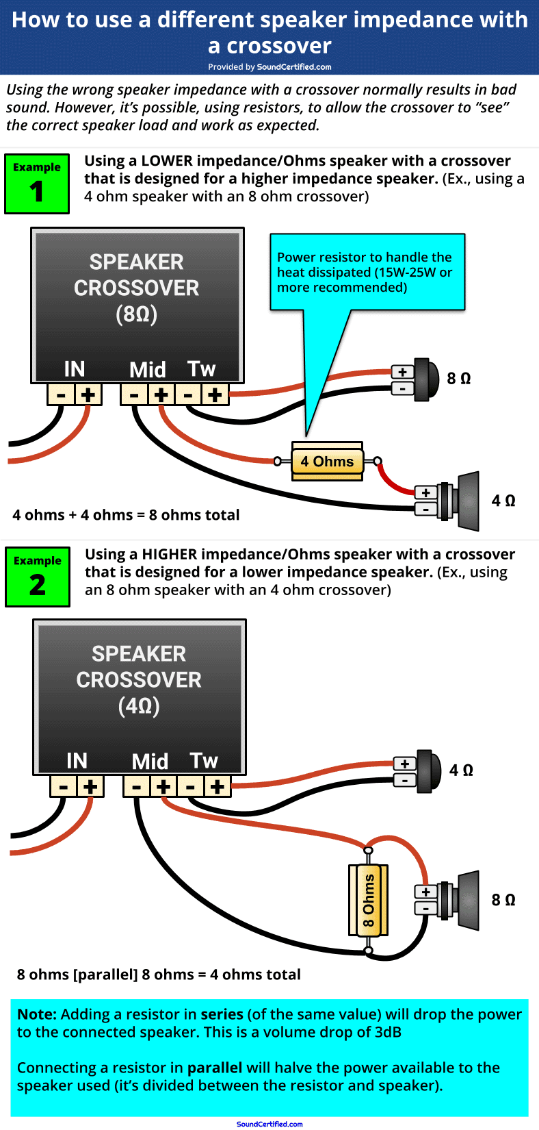
- Case #1: a speaker that has a lower impedance: You can add a resistor in series with the speaker to bring the total Ohms load up to what the crossover needs. You’ll need a resistor with enough power handling (called a “power” resistor) to avoid it overheating (see below).
- Case #2: a speaker that has a higher impedance: You can add a resistor in parallel with the speaker to bring the total Ohms load down to what the crossover needs.
Examples:
- You can use an 8 ohm speaker with a 4 ohm crossover by connecting an 8 ohm resistor in parallel with it. The end result is 8 Ohms/2 = 4 ohms the crossover will see.
- You can use a 4 ohm speaker with an 8 ohm crossover by connecting it in series with a 4 ohm resistor. The end result will be 8 ohms total seen by the crossover.
What is a power resistor?

Examples of power resistors commonly used with speakers. Unlike the tiny resistors used in electronics, these can handle much more power and won’t burn up due to heat. They’re available from electronics suppliers including speaker component retailers.
A power resistor is just a larger-size resistor that can handle a lot more power & heat than the small ones commonly used on electronic boards. They’re actually fairly inexpensive, too ($5 or so for 2 to 4 in a pack) and are commonly used for custom speaker projects.
For speaker systems, I recommend using one with a power rating of 25 watts or more to be sure. For car stereos, you can often get away with around 10W to 15W, however.
The drawbacks of using resistors to match a crossover
Like I said earlier, it’s not without a compromise. You’ll have to live with a few things depending on which case you’re dealing with:
- Adding a resistor in series with a speaker will drop the maximum power & volume available to it. In the case of a 4 ohm speaker and a 4 ohm resistor, this means you’ll lose 3 dB of volume (a tiny amount) but the power will always be 1/2 of what it used to be.
- Adding a resistor in parallel with a speaker means the power will be split between the two. In the case of an 8 ohm resistor parallel with an 8 ohm speaker, a each side will receive 1/2 of the power formerly sent to one speaker. (Ex.: a 50W amp would now deliver 25W max to the speaker)
Ordinarily, I’d recommend using the correct crossover but if you’re “in a pinch” this solution is a great way to get your speakers going and still sounding good.