Ready to design and build your own speaker crossover? You’re in the right place!
Here’s a very easy-to-use speaker crossover calculator along with great info to help you.
Note: Javascript must be enabled in your browser to see or use the tool.

Contents
SPEAKER CROSSOVER CALCULATOR
You can use my speaker crossover calculator to generate parts values to build your own capacitor, experiment with different values, and more.
How to use the calculator
- Select the crossover type:
- 4 types are available: 2-way 2nd order Linkwitz-Riley (12dB/octave), high or low-pass 1st order Butterworth (6dB/octave), 1st order 2-way Butterworth (6dB/oct.), and 1st & 2nd order 3-way crossovers.
- A speaker crossover schematic matching the type you chose will be shown.
- Enter the speaker impedance (Ohms) as needed. This can be whole numbers, fractions, or both. (Ex.: 4 ohms, 3.6 ohms, etc.)
- Enter the crossover frequency desired. For 3-way crossovers, enter the bandpass upper (tweeter/midrange) and lower (midrange/woofer) cutoff frequencies. (*See my notes below regarding 3-way crossovers below.)
The calculator will output capacitor and inductor part values as needed. Parts are labeled to match the the example schematic shown for each type you select.
Reversing out of phase speakers for even-order designs
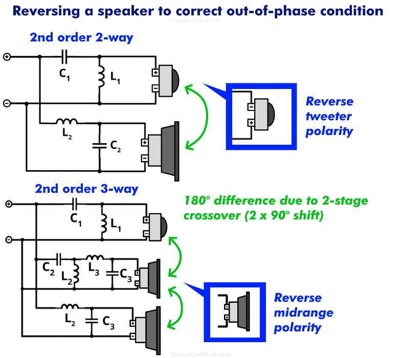
When building a speaker crossover and using a 2nd order or other even-order designs, it’s important to remember to reverse one speaker driver to correct the 180 degree out of phase condition.
Crossover capacitors and inductors each add a 90° phase difference, giving 2nd order crossovers a 180° out of phase condition that will affect the sound.
An out of phase condition can result in destructive interference (sound wave cancellation) in the overlapping range of sound between two speakers (three speakers in the case of a 3-way system) near the crossover frequency. It will also sound “weird” because the timing of the audio waves you hear conflicts.
For example, you can hear the same effect if two speakers are placed near each other with one having its speaker wiring reversed. In that case, you may notice poor bass until one speaker is disconnected due to cancellation.
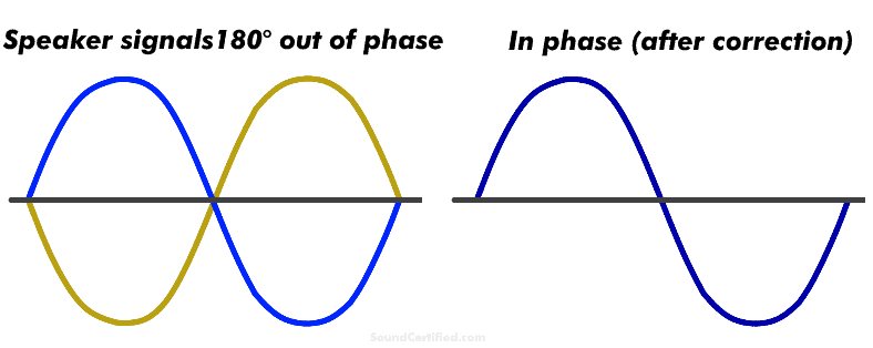
Image showing 180 degree out of phase audio waves and the resulting in-phase (0° difference) condition after reversing the speaker.
Fortunately, there’s an easy fix:
- For 2-way crossovers, reverse the tweeter connection polarity.
- For 3-way crossovers, reverse the bandpass speaker (midrange speaker) polarity.
You can do this by reversing the wiring at the speaker terminals in the crossover building stage or reversing the connection polarity label once it’s completed.
This is almost never a problem for ready-made crossovers you buy as this is usually already taken into account when they’re designed.
Why use a Linkwitz-Riley crossover for 2-way crossovers?
Linkwitz-Riley designs are hands-down one of the most commonly used for a number of reasons, one of which is their flat response where the woofer and tweeter crossover points overlap. While it’s true that plenty of other designs exist (Butterworth, Chebychev, Bessel, and others) they do not offer the same frequency response.
They certainly have useful applications but the Linkwitz-Riley (L-R) crossover is generally a great choice for standard speaker systems with a -12dB per octave slope.
The flat magnitude response, low sensitivity to offset, and in-band driver resonances have made the L-R a popular choice among manufacturers.<span class="su-quote-cite">Vance Dickason, <em>The Loudspeaker Design Cookbook </em>(7th ed.)</span>
It’s also not sensitive to speaker driver resonance like some others. If you’re interested in the technical aspects of the different crossover designs available, I’d encourage you to read more.
I highly recommend Vance Dickason’s The Loudspeaker Design Cookbook for more detailed information as it shows examples and covers the topic in good detail. You’ll also learn tons of other speaker design info!
3-way crossover details for the calculator
To get the best results (3-way crossovers are NOT simply an extension of 2-way designs), the calculator uses a 3-way all pass crossover (APC) design with a sufficient frequency range between the high pass frequency and the low pass frequency.
You can also use a general rule based on the ratio of the high pass cutoff (Fh) and low pass cutoff (Fl):
Some great example 3 way frequencies to use are:
- 3kHz/375Hz
- 5kHz/625Hz
- 6kHz/750Hz
Or, simply pick the upper frequency and divide by 8 to get the 2nd. Likewise, you can pick a lower frequency and multiply by 8 to get a good upper frequency.
However, do be aware that 3-way designs have a midrange output with a higher or lower dB level – in this case, the 3-way design provided has a 2.45 dB gain vs the tweeter and woofer. (This is a pretty minor difference however)
Crosspoints closer together than the three-octave ideal will suffer from complicated undesirable interference patterns.<span class="su-quote-cite">Vance Dickason</span>
Consider adding a Zobel network and series notch filter

Want even better results from your speaker system? Consider adding a Zobel impedance compensation network and in the case of midrange & tweeter drivers a series notch filter. Those will tame nasty impedance issues:
- The steep impedance rise at higher frequencies due to voice coil inductance.
- Very high (peak) Ohms at the resonant frequency “Fs.”
I cover all this on my Zobel network and series notch filter calculator page.
How precise do crossover capacitor and inductor part values need to be?
 I recommend trying to get fairly close to the calculated parts values; exact values are not practical or needed. For example, if the calculator recommends a 10.56mH (milliHenry) inductor, you’d try to get close to 10.5 mH, not 10.56mH. If you found a 10.2mH for example, that would usually be close enough.
Similarly, for the parts themselves, standard tolerance parts are fine for most designs. You don’t need to spend additional money on better tolerance components.
Of course, that doesn’t mean you shouldn’t use better quality or higher performance parts if you’d like – just that for most cases standard (20% – 15% tolerance) is fine.
Typical inductor and capacitor tolerances
The truth is that picking super-precise part values is kind of useless anyway because the components have as much as a 20% tolerance. For example, a 4.7 µF (4.7 microFarad) non-polarized capacitor, 20% tolerance, could have an actual capacitance as low or high as:
- Low end: 3.76 µf
- High end: 5.64 µF
As you can see, trying to pick the perfect parts values doesn’t make sense because they won’t be exactly that value anyway. That’s out of your control. Just try to get it pretty close if possible.
Most inductors are similar as well – especially air core wire wound inductors.
Affordable ways to get better sound performance
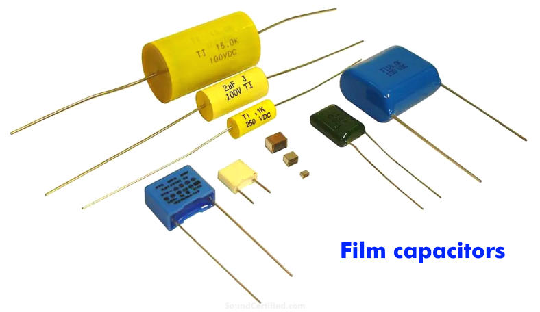
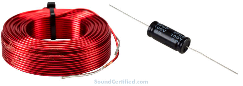
Electrolytic capacitors are extremely common in speaker crossovers and filters..but did you know? There’s another little-known way to get better sound and better parts quality without spending a lot: polypropylene, polyester, and film capacitors.
They offer some nice benefits for only a little bit more money:
- Longer life/don’t leak over time like electrolytic capacitors
- Higher voltage handling (great for vacuum tube designs!)
- Better audio performance (better for carrying the audio signal)
- Vertical solder leads may make them easier to use in printed circuit boards or DIY projects
- Some film capacitors are more compact than their counterparts
Film capacitors are generally bipolar (non-polarized) so they’re great for audio designs, but it’s important to always check the specs to be sure.
Also, be sure to verify their voltage rating – you’ll want a rating that’s at least equal to or higher than your amp or stereo’s output voltage generally.
Inductor options
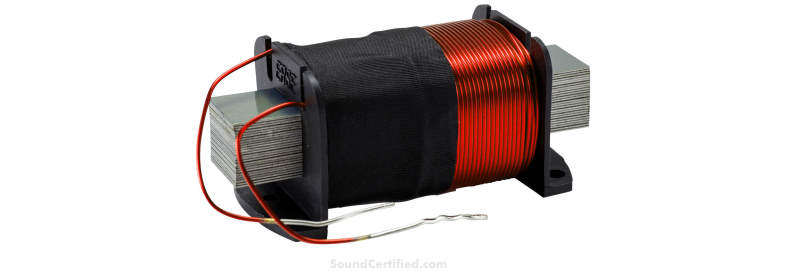
They’re not mandatory, but you can also consider using iron core or metal-core inductors. These types have a more dense magnetic field characteristic, meaning they can be a bit smaller than air core models in some cases.
What voltage audio capacitors do I need?
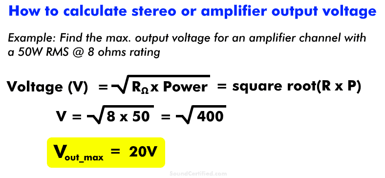
There’s an easy way to find the voltage rating for audio capacitors in crossovers: you can find the approximate stereo amplifier or radio output voltage if you know the power per channel (RMS or continuous) and speaker Ohms.
Simply use this formula: Volts = square root(Speaker Ohms x Max. Continuous/RMS Power)
This will give you the approximate voltage at maximum output power. Once you know that, I recommend using capacitors with a voltage rating at least the same, if not higher, voltage rating.
Otherwise, for standard power levels (not using maximum power out), you can use the next closest value.
Off-the-shelf bipolar capacitors sold for audio applications are normally of a sufficient working voltage. Still, it pays to check. Lower voltage bipolar parts (5V, 16V, etc.) are usually used for low-voltage (line level) electronics.
TIP: adjusting the crossover frequency to match parts on hand
Here’s a helpful tip I’ve picked up after building my own crossovers. If you’ve got parts on hand you’d like to use you might be able to do so by slightly changing the crossover frequency.
For example, let’s say you use the calculator for a 2-way 2nd order design at 3,000Hz, 4Ω:
- C1, C2 = 6.63uF
- L1, L2 = 0.42mH
Let’s also say you have some capacitors on hand that are below 6uF. By changing the crossover frequency slightly, you can sometimes use parts you already have.
Obviously this won’t always work, and not all speakers are suited for it, but it’s a helpful strategy in some cases. Using a calculator, you can play around with values in seconds and see what works.
Question… let’s say I’m building a 3-way speaker. The tweeter is 8ohms, the mid is 4ohms and the woofer is 8ohms. What do I do to ensure the output is a specific rating (in my case, ideally 6 or 8ohms)? Is this just a matter of wiring the speakers in series or parallel, or is there another component that I can use in the crossover to enforce it?
Thank you in advance. This article is great!
Hello TJ. In this case, to ensure you keep an 8 Ohm load, you could:
1. Add a second 4Ω midrange in series with the first.
2. Add a 4Ω power resistor in series with the midrange.
Option #1 is a bit more ideal, as option #2 means 1/2 the midrange power will be wasted as heat across the resistor. If your amplifier or receiver needs a minimum 6Ω load, then using the 8 Ohm load will be fine. (If that is what you meant).
Best regards!
Thanks Marty!
I was more curious than anything else. I wasn’t exactly sure what approach would be better but your explanation makes perfect sense. I’d rather use the power than have it being wasted on heating up the resistor. In this specific case I would probably run the two 8ohms in parallel (drop to 4ohms) and then connect them in series with the 4ohm mid to bring it back to a consistent 8ohm load.
I am a woodworker and have been a bit of an audiophile for most of my life, so I’ve decided to build my first pair of speakers from scratch. I have some beautiful wood and several different drivers to work with so it’s time to get the whole crossover thing down. Your articles are very helpful. Advanced enough for someone who isn’t quite a beginner (I do have some engineering in my background) without getting too technical. I’m sure I’ll be back once I start testing out the speakers to look more in to Zobel network.
Until then…
I have the klipsch rp450c, it has 1x horn tweeter and 4x 5.25 woofers its a 2.5way design. Can I build or order a new crosser over for a 3 way design using the same amount of speakers?
[link..]/klipsch-rp-450c-review/ link has the details on the center speaker.
Hello, Jay. You can do that, just you’ll need to wire the woofers according to their Ohms rating.
For example, with 4 woofers, some solutions are:
• 8Ω woofers: wire sets of two in series (16Ω), then those in parallel. 16Ω || 16Ω = 8Ω total.
• 2Ω woofers: wire in series for 8Ω total.
You could do this for a 2-way design or add a midrange for a 3-way design, either way. Best regards.