We take for granted how certain stereos and amplifiers need 2, 4, or 8 ohm speakers to work right. But what is speaker impedance?
And how can you tell the impedance of a speaker if it’s not on the speaker or you can’t find it?
Great news – it’s not that hard! In this helpful article, I’ll explain how speaker impedance works, how you can measure speaker impedance (Ohms), and much more.
There’s also a handy speaker Ohms chart to help you identify what impedance your speaker is to know for sure.
Contents
- How to tell the impedance of a speaker
- What is speaker impedance? (Speaker Ohm ratings explained)
- How to measure speaker impedance
- How to measure speaker impedance when there is a crossover
- Speaker impedance example chart (use with speaker measurements)
- What happens if my speaker impedance is too low or too high?
- Speaker impedance and crossovers – yes, it’s important!
How to tell the impedance of a speaker
Let’s cover the main ideas before going into more detail as I cover each topic more.
- If the Ohm rating (impedance) is not available on the speaker, you must measure the impedance of a speaker using a test meter set to the Ohms (resistance) function. This will give the resistance of the voice coil which will let you determine the speaker’s impedance category. (see below for more detail)
- A speaker’s impedance is usually listed on the speaker magnet, packaging, and/or box and specifications. This is not always the case, however, as it depends on the manufacturer and model.
- The total impedance changes with frequency as speakers don’t act like resistors but instead have inductance which opposes the flow of current as the audio signal frequency increases. You can calculate impedance based on the formulas included here. Note: you won’t need this just to determine the general impedance range of your speakers.
Long story short, if your speaker doesn’t have the impedance listed anywhere or you can’t find the manufacturer’s specs, the best thing to do is to measure it. That way you can be 100% certain and avoid problems with your stereo, amplifier, and crossovers.
You definitely don’t want to use a speaker with lower impedance than expected as it’s possible to damage your stereo or amplifier permanently!
What is speaker impedance? (Speaker Ohm ratings explained)
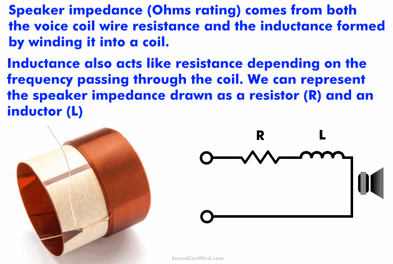
Speaker impedance, measured in Ohms, is the voice coil’s total resistance to the flow of electric current as it operates with a musical signal.
Unlike standard electrical conductors, the voice coil’s wire winding forms a loop that has an electrical property called inductance. Inductance is different from resistance as it changes as the frequency changes. This is called inductive reactance.
How does speaker impedance work?
Magnetic fields are created as current flows through the tightly wound wire coil. These fields have an opposition (resistance, also called reactance) to the current flowing through the coil wire. (Similarly, many other electrical components like motors have this too).
Because of how inductance works and the physics involved, the speaker “impedance” (total resistance) isn’t a simple addition of the resistance and the inductive reactance together.
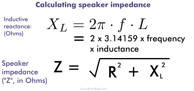
Instead, speaker impedance is found from the algebraic sum (the square root of the sum of the squares) of the coil’s wire resistance and the inductive reactance.
Inductive reactance is commonly written as “Xl”, pronounced “X sub L” and is measured in units of Ohms just like resistance. Inductance is measured using a unit called the “Henrie” and commonly noted with an “H”: “uH” for microHenries, “mH” for milliHendries, and so on.
How to calculate speaker impedance
If you’re a math person, you can see here how speaker impedance is calculated. As I mentioned, it’s the geometric sum of the resistance in the voice copper wire winding and the inductive reactance at a given frequency.
The most important thing to understand about speaker impedance is:
- The speaker impedance is always equal to or greater than the voice coil wire resistance. You can measure this with an Ohm meter.
- The impedance number on a speaker is a general guideline for compatibility, not exactly what the speaker measures.
- The impedance changes slightly (goes up) as the frequency being played increases.
In fact, if you were to use a test meter to measure the Ohms (impedance) of the voice coil on a speaker, you’d find a reading of about 3.2-3.6 ohms or so for a 4 ohm speaker and 6 ohms or higher for an 8 ohm speaker.
Example of calculating speaker impedance
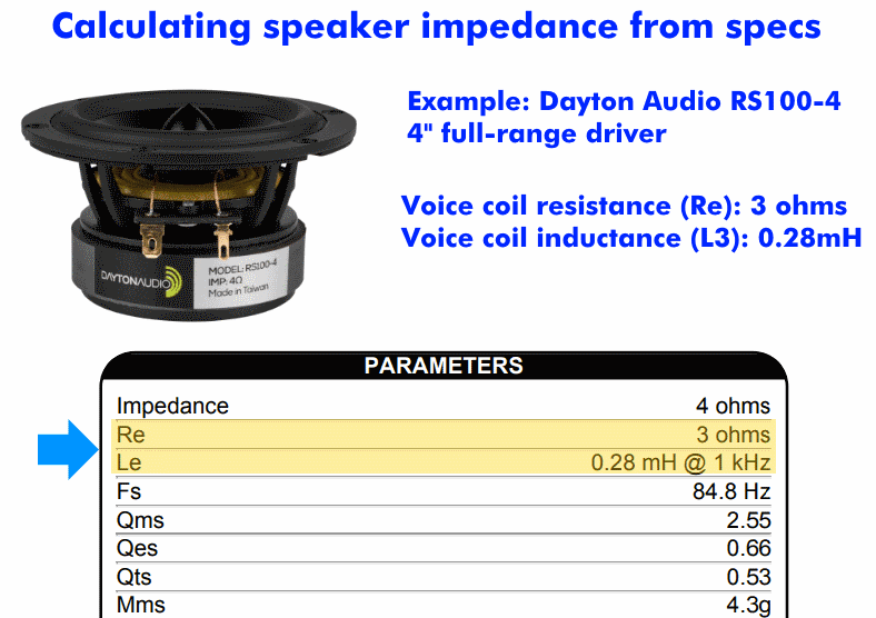
Let’s take an example. We’ll use an example speaker and real-world specifications then do the math.
Example parameters to use from a real speaker for the voice coil’s resistance (Re) and the winding’s inductance (Le).
Example of calculating the speaker impedance using 1kHz as the frequency:
- Calculate the inductive reactance:
Xl = 2*Pi*Le*frequency: 2*3.14159*.000280*1,000 = 1.759 Ohms (Ω) - Find the total impedance (represented by “Z”): Find the square root of the sum of the squares of Re and Xl:
Z = √[ ( (3.0)^2 + (1.759)^2 ] = 3.142 Ohms (Ω)
Therefore, for our example speaker, the total impedance at 1kHz is 3.142 Ω, only a little bit higher than the voice coil’s own resistance.
This is because (1) most speakers have a very small amount of inductance, and (2) speakers work in the audio range and no higher than 20kHz, meaning the inductive reactance will be limited.
Speaker impedance due to the resonant frequency
That’s not to say that speakers never have a high impedance. In fact, at their resonant frequency where they behave differently, the impedance can be HUGE! In fact, as high as 50 ohms. However, that’s a separate topic.
(Note: as you see from the example speaker’s specs, the parameter “Fs” tells us the resonant frequency of 84.8Hz is where that happens for this particular speaker)
How to measure speaker impedance
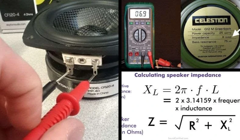
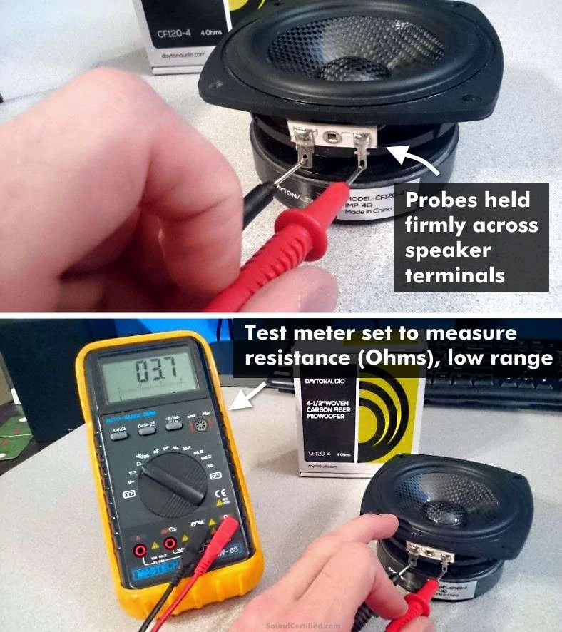
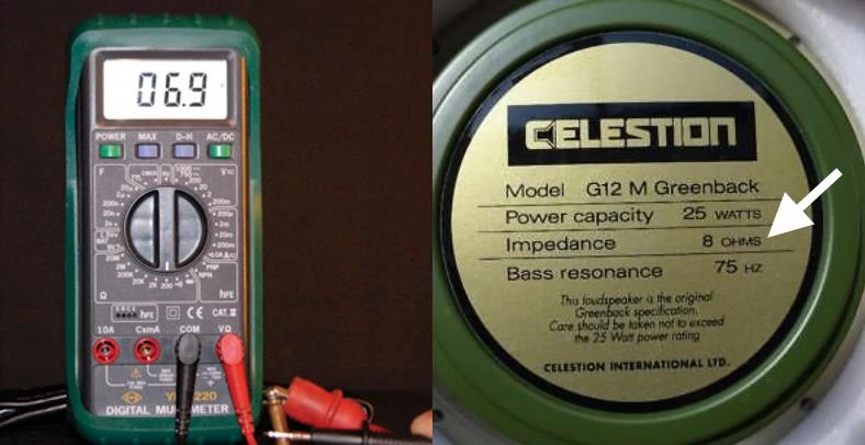
In this picture, you can see an example of how to measure speaker impedance using an Ohm meter or any standard test meter set to measure resistance in Ohms. To do so, set it to the lowest range that measures units of 1, 0-10, 0-20, or auto-ranging and the meter will measure it accordingly. Hold the test probe leads firmly against clean metal on the speaker terminals with speaker wire removed.
To measure the impedance of a speaker you’ll need a multimeter (test meter with multiple functions) or a dedicated Ohm (resistance) meter.
Use the following steps:
- Switch on the meter and set it to measure Ohms on the lowest range. This is often the x1 range, 0-10, 0-20, or auto-ranging setting.
- Disconnect one or both speaker wires from the speaker to avoid a false reading due to other resistance that may be connected to it.
- Hold the probes firmly against the speaker terminals on a clean, bare metal spot. The meter should quickly settle to a reading. The meter will show the resistance of the voice coil inside the speaker.
- Use the measured value to determine the closest approximate speaker impedance (see my chart below for help).
- For speakers inside a cabinet or enclosure such 2-way speakers, crossovers may be in use and these can interfere with this reading with a few exceptions. However, in many cases, you still measure the resistance of a woofer fairly well.
The important thing to bear in mind is that you won’t measure exactly 4 ohms, 8 ohms, etc. Speakers are given an impedance rating for stereo purposes that are approximate – or close to – what you’ll measure with a test meter.
See my notes below for how to measure those correctly.
Selecting the correct resistance (Ohm) range for speakers
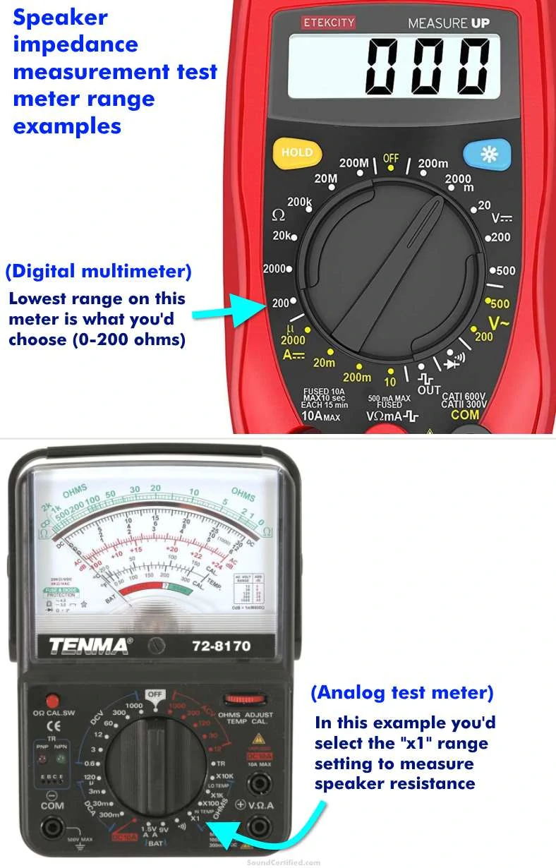
Shown are some example test meter resistance range settings to use for typical test meters.
As I mentioned earlier, it’s important to use the correct resistance range on your meter when measuring speaker impedance. That’s because the wrong setting may display nothing or give you the wrong idea that perhaps the speaker is blown when it isn’t.
If you’re not sure, check the test meter’s manual. Many modern digital meters often have an auto setting that will automatically adjust for the Ohm measurement it detects and will display the reading & decimal places accordingly. Other meters require you to select the correct range manually.
As a general rule, use the lowest range that includes 0-10 ohms (or similar) then go up if necessary.
That should almost never happen – but in the case of a poor connection, blown (or almost blown) speaker, strange things can happen and you might get a reading that’s far outside the speaker’s normal impedance.
In my experience, however, that’s very rare.
Once you’ve got your measurement, use my speaker impedance chart to find the next closest speaker impedance value listed.
How to measure speaker impedance when there is a crossover
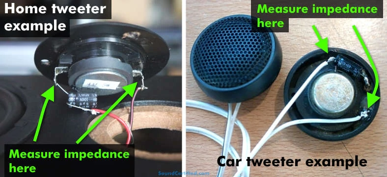
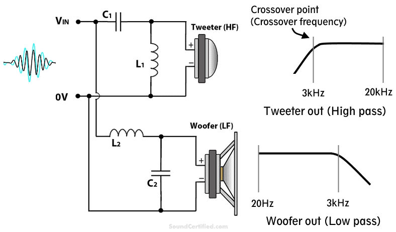
Tweeters are one of the most common types of speakers with a crossover. To measure speaker impedance on them, you’ll need to place the test meter’s probes around the capacitor crossover. Otherwise, the reading will be an open circuit or far too high.
Measuring speaker impedance where crossovers are used is a bit of a problem. That’s because capacitors, which are commonly on tweeters as a high-pass filter, act as an open circuit when measuring resistance.
Obviously, that’s a problem as you’ll never get a correct reading if you use the test leads on the speaker wiring.
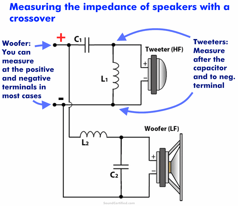
To avoid this, you’ll want to measure around the capacitor, if used, which is normally on the positive speaker terminal. You should be able to then get a correct reading.
For 2-way speakers, in many cases, no crossover is used on the woofer. In some cases, there’s an inductor in series with it. The good news is that directly reading resistance across a speaker and an inductor doesn’t make much difference – inductors have a tiny resistance value. In fact, they’re usually in milliOhms (thousandths of an Ohm) which is almost nothing.
For 2-way crossovers, the same applies, too. Following the diagram above, your main concern is avoiding measuring across capacitors.
Speaker impedance example chart (use with speaker measurements)
An 8 ohm speaker, in the real world, will have a resistance measurement less than its 8 ohm rating. That’s normal and is due to how the speaker is made. Speakers do not have exact impedance values but instead will fall into a general range close to their rating. You can use that range to identify their impedance if you don’t know it.
To use this chart, take the speaker resistance measurement you got from the instructions earlier and use it to compare to the measurements here. You’ll see your speaker should fall into of the commonly sold speaker impedance standards.
Speaker impedance measurement chart
| Speaker measurement range* | Speaker impedance rating |
|---|---|
| 3.1-4.0 ohms | 4 ohm |
| 6.0-8 ohms | 8 ohm |
| 1.2-2 ohms | 2 ohms |
| 4.0-6 ohms | 6 ohms |
| 0.5-1.0 ohms | 1 ohm** |
| 12-16 ohms | 16 ohms** |
*(This is an approximate range and should cover nearly all speakers but may vary slightly)
**(1 ohm is rare but can be found in some car stereo products such as Bose premium amplified systems. 16 ohm speakers may sometimes be used for home or other speaker systems, but aren’t very common)
What happens if my speaker impedance is too low or too high?
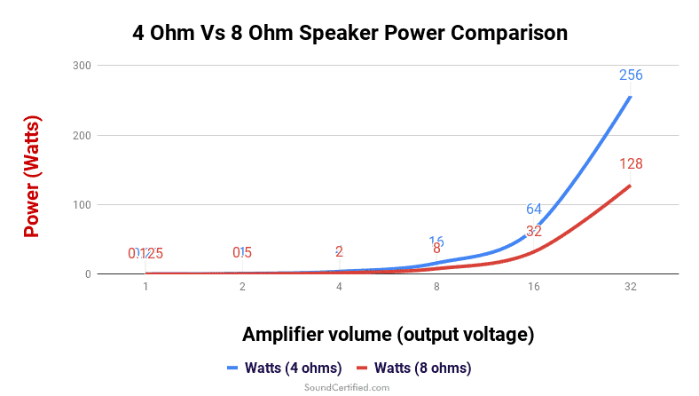
This graph shows what happens when a higher impedance speaker is used with an amplifier or stereo rated for a lower impedance speaker. As this example shows, using an 8 ohm speaker in the place of 4 ohm ones means it will develop 1/2 the power and consequently, lower volume than a 4 ohm speaker.
Using a speaker that’s not matched to the stereo or amplifier it’s rated for can have relatively minor – or even horrible – results depending on which case we’re talking about:
- Using a higher impedance speaker won’t damage equipment. The result will be lower power developed and therefore lower possible volume. You may also introduce problems with speaker crossovers, however.
- Using a lower than specified impedance speaker will cause radios or amps to suffer extreme heat and even permanent damage because the current output will be much more than what it’s designed for.
For example, if you were to use 8 ohm speakers in the place of 4 ohm car stereo speakers you won’t damage anything, as less current will flow to the speaker. The problem will be (although it will play fine, otherwise) is that the total power available will be 1/2 that of a 4 ohm speaker.
Ohm’s Law and speaker power
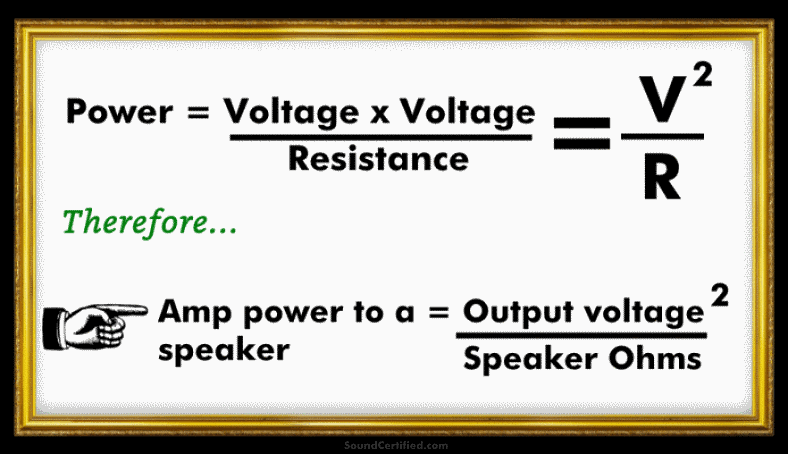
A radio or amplifier is designed to output a certain voltage level for a given volume and so higher impedance speakers won’t have the same power available at the same volume level. That’s because the power to a speaker depends on the voltage available.
By the electrical formulas called Ohm’s Law, P (power, in Watts) = Voltage^2/R (speaker Ohms)
For a low volume (2V output from an amplifier) a 4 ohm speaker would have 1W of power available. An 8 ohm speaker, however, would have only 1/2W. That means for the same amplifier or radio volume, higher impedance speakers can’t produce the same volume.
How does speaker impedance affect sound?
Using the wrong speaker impedance can affect the sound in a few ways:
- If you mix and match 4 ohm tweeters with 8 ohm woofers, for example, they’ll be mismatched and at some point won’t sound right as the power increases because their volume levels won’t be the same.
- Using the wrong speaker impedance with speaker crossovers can have a very big impact on the crossover frequency (it will be shift a lot) and will dramatically affect the sound output. Your speakers won’t sound right, can have a lot more distortion, and will generally be much less pleasant to listen to.
What happens to a car stereo if a speaker has a lower impedance than the stereo is rated for?
Using a lower impedance speaker than your stereo or amplifier is rated for is a terrible idea and should never be done! That’s because it’s not designed to handle the excessive amount of current it will have to supply thanks to the decreased resistance of the lower speaker impedance.
If you’re lucky the unit will go into “protect mode” in which it shuts off until the condition is removed and it’s safe to operate. However, from my experience, many electronics become extremely hot and can burn out their output transistors meaning they’re permanently damaged.
Don’t risk it! Always check the minimum Ohm rating of your equipment and be sure to follow it. Never assume the amp, radio, or receiver, etc, will be able to protect itself from damage.
Speaker impedance and crossovers – yes, it’s important!
Crossovers are designed for a specific speaker impedance. Changing the speaker impedance means you’re changing how they function and shifts the crossover frequency, giving worse sound and potentially adding distortion that wasn’t there before.
When using speaker crossovers, it’s really important to understand that you can’t change the speaker load (speaker impedance they see connected) as the results won’t be good.
Changing a 4 ohm speaker to an 8 ohm one, or vice versa, will have a huge impact on the sound because the crossover cutoff frequency will change greatly since it depends critically on the speaker load used.
As a general rule:
- Doubling the speaker impedance will halve (decrease) the crossover frequency.
- Halving the speaker impedance will double (raise) the frequency cutoff.
For tweeters, increasing the tweeter impedance means you’ll be allowing in more bass & midrange, leading to poor sound since tweeters can’t produce those ranges. For woofers, that means introducing poor-sounding midrange or treble that they’re not suitable for.
In both cases, just remember that the crossover frequency changes inversely proportional to the speaker load you’ve increased or decreased.
