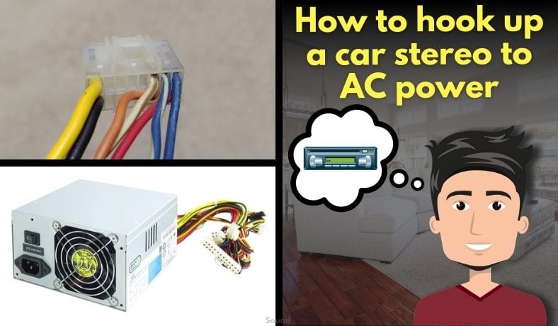
Want to use your car stereo at home? Great news – it’s actually not that hard…if you know what you’ll need.
In this article, I’ll show you how to hook up a car stereo to AC power along with:
- What you need to know first
- Clear & easy-to-follow wiring diagrams
- What kind of AC power adapters or supplies you can use
- How to wire a computer power supply to a car radio

Contents
- First things first: can you hook up a car stereo to a house outlet?
- What can I use to power a car stereo at home?
- How do you hook up a power supply to a car radio?
- How to wire a computer power supply to a car stereo
- How to wire a car stereo and DC power supply to avoid losing memory presets
- How to connect car stereo wires together properly
First things first: can you hook up a car stereo to a house outlet?
The quick answer is yes, with the right power supply, you can hook up a car stereo to a house outlet with 120V or even 220V power. You cannot, however, directly connect a car stereo to an outlet.
However, you’ll need to know just a few things to make sure you don’t have any headaches or potentially destroy your car stereo.
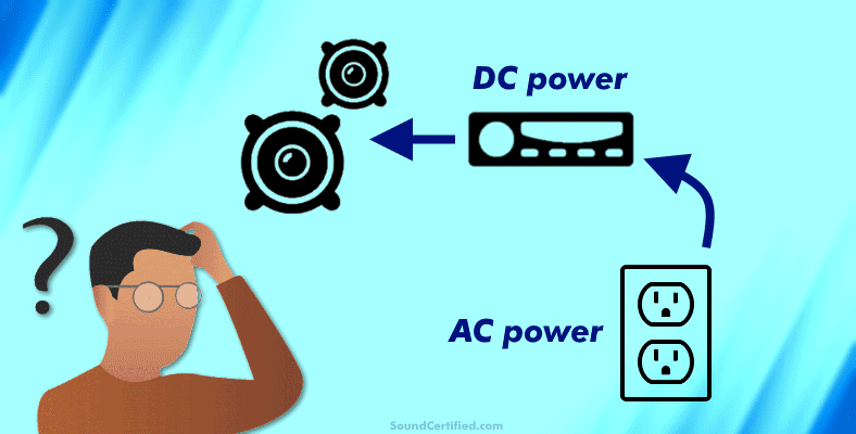
Is a car radio AC or DC?
Car radios use direct current (DC) voltage to power their electronics while home electronics use alternating current (AC) with a much higher voltage. In fact, car radios can work down to somewhere around 11 volts DC, with 12V to 14.4V being typical when a vehicle’s engine is running.
The reason car radios use DC power is that automobiles use a DC battery to start and power the engine. While the motor is running an alternator generates AC power that’s changed to DC in order to charge the battery. Batteries store DC power, not AC.
What voltage do home outlets use?
Home AC outlets supply around 120V (volts, or “V”) AC if you’re in the United States and some other countries. Others I’ve been to are even higher at 220V AC. It’s extremely dangerous to try and connect a DC device to AC power – in fact, it can even explode or catch on fire.
What you need is a power supply to safely reduce the high voltage of a home AC outlet to a lower DC voltage that a car stereo can use.
How many amps does a car stereo draw?
The good news is that unlike car amplifiers, a car stereo draws only a few amps. Typical car stereos (depending on the design, features, etc) draw about 2 to 5 amps or so at full power.
I’ve seen some units that have a 10 amp fuse, but that doesn’t mean they use quite that much current. Fuses come in certain sizes so that’s the next closest one the manufacturer needed to use.
Although car stereo manufacturers may advertise them with high power ratings like “50W peak per channel”, in reality, the average car stereo can only put out about 15 to 18 watts RMS per channel.
That’s because they have to work with a +12V supply which limits the power they can deliver.
What is the 12V accessory wire on a car stereo?
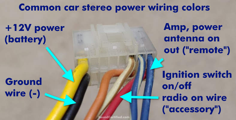
Car stereos have 3 power wires that have to be connected in order to work:
- Ground/negative, “GND”
- +12V power/radio memory backup “BATT”
- Accessory on, “ACC”
For 99% of car stereo, the 12V accessory wire is a red-colored signal wire that triggers the electronics to switch on. They’re normally connected to a vehicle’s ignition switch accessory wire to turn on and off with the switch.
It’s necessary to connect this to power on a car stereo. When power is removed from the radio’s accessory wire it turns off and goes into a low power mode.
What can I use to power a car stereo at home?
The good news is that 12V power supplies are available if you look in the right place – and one that’s right for hooking up a car stereo to AC power shouldn’t cost much. You just need to know what to look for.
The good news is that it’s usually not hard to find the right kind of supply to power a car stereo at home. You’ll need one with 2 main things:
- The right voltage: 12V to 13.8V
- The right current (amps) rating: about 2 to 2.5A for most car stereos and towards 5A for some units that draw more
12V supplies are usually a lot more affordable, anyway.
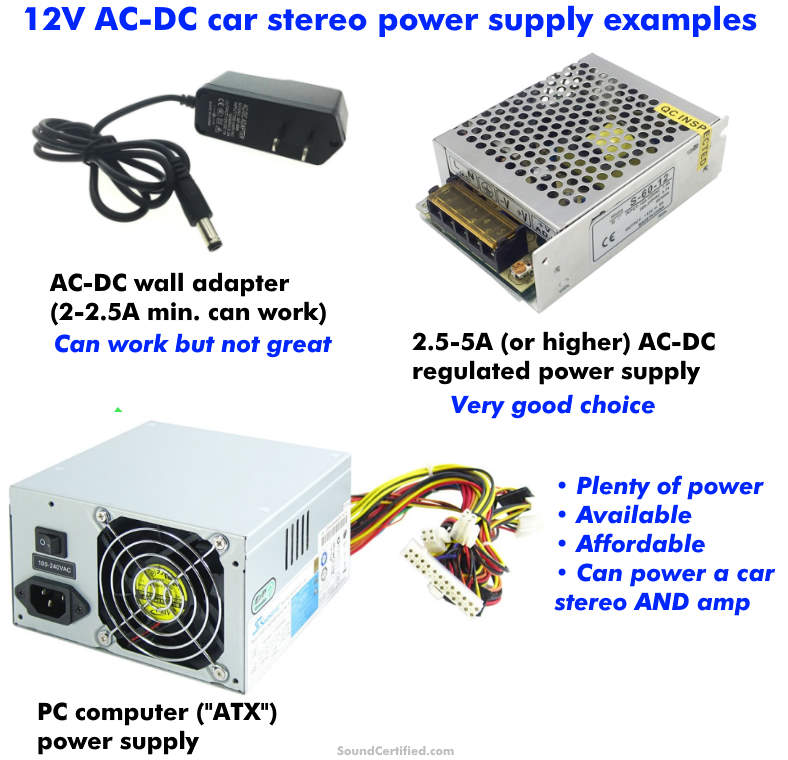
You can pick up an AC-DC supply from a variety of places: Amazon, your local electronics store, and you can even use an old PC computer supply (also called an “ATX” supply) you’ve got lying around. I’ll cover that in more detail later.
Can you use a wall adapter for a car stereo?
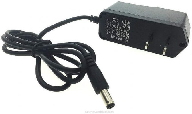
While you can use a wall adapter to power a car radio with decent results, most are pretty poor and can’t supply many amps and only a little bit of power. You’ll also need to cut the wiring which in some cases can be a little tricky since it’s sometimes very small wire.
Technically, you can use a wall outlet AC-DC 12V adapter, but I don’t recommend it.
They’re pretty limited in power output and the amperage they can provide (many are less than 1A rated). They’re designed to do things like charge devices or supply low-power devices.
They also don’t have good reserve power and when you start cranking up your car radio the voltage may begin to sag (drop out) and it won’t work well along with the sound breaking up & distorting. You’ll need to find one with enough current (say 2 to 2.5 amps or more if possible) and cut the wiring since most come with a connector attached.
Always be 100% sure before connecting a radio to avoid a reverse polarity condition as that can damage electronics!
What to know about computer power supplies
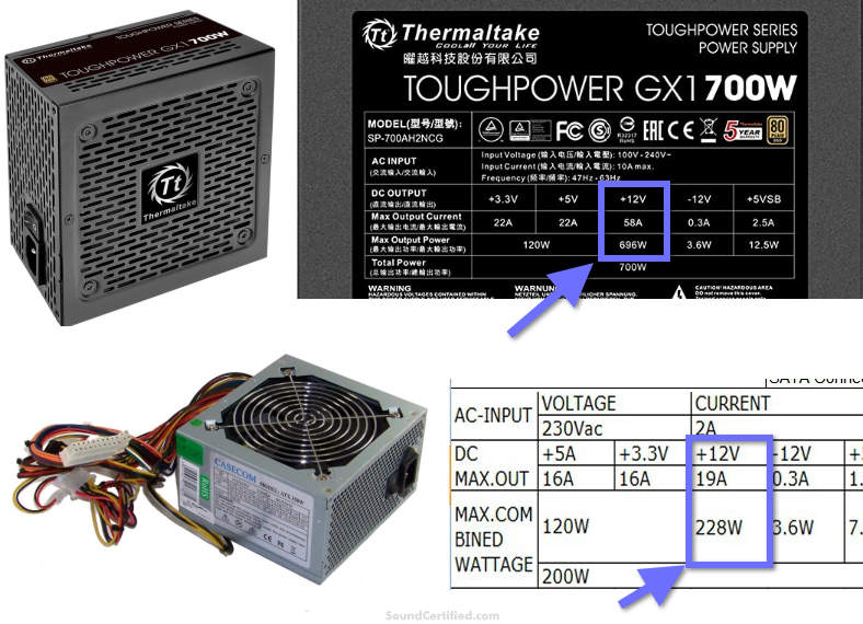
PC power supplies are also called “ATX” supplies and can provide lots of current from their 12V wiring. You can see their amp output rating on the label like the examples above.
Computer power supplies are relatively common and usually priced well (especially used). You won’t need a high-power one.
In fact, even a standard low-end 150W PC power supply will work great for a car stereo! Nearly all of them have more current output than you need.
The drawback, however, is that PC power supplies require a certain (but easy to do) wiring connection in order to turn on. That’s because they’re normally connected to a PC motherboard that provides a control signal for them to work.
Fortunately, you can use an easy workaround that makes them great for a home car stereo system power source. See my detailed diagram for that further below.
How do you hook up a power supply to a car radio?

Connecting radio power and ground
To connect a car radio to a power supply you’ll need to do the following:
- Ground: Connect the radio’s ground wire (black wire) to the (-) power supply output
- Main power: Connect the radio’s +12V battery wire (usually the yellow wire) to the (+) power supply output
- Turning the radio on: You can do this by hardwiring the radio’s accessory wire (usually red) to the +12V battery wire or you can use a switch in between.
If you hardwire the accessory wire to the yellow wire (battery power), you can turn the car stereo off with the power supply on/off control. However, while that’s very easy, it comes with a price.
Removing power from the 12V battery wire means the unit will lose its radio tuner settings, audio settings, and any other adjustments you’ve made. Optionally, using a switch to connect the accessory wire as an on/off control is a good idea. Leave the power supply on in this case.
Another way is to simply turn the radio on/off using the power button and leave the power supply on. In either case, when turned off the radio will go into a low-power mode draw less than 0.5 amps when shut off.
Connecting the speaker wiring
Car stereos usually use standard wire colors for speaker connections:
- White = Front left +, White/black = front left –
- Gray = Front right +, Gray/black = front right –
- Green = Left rear +, Green/black = left rear –
- Violet = Right rear +, Violet/black = right rear –
Just like power wiring colors, not all brands follow these standard colors so always check first!
Remember that car stereos can’t handle a speaker impedance (Ohms speaker load) below 4 ohms. You can, however, use 8 ohm home stereos speakers although you’ll only have 1/2 the rated output power available. I’ll explain that further below.
Never connect 2 ohm speakers for example or wire speaker outputs together as the radio can become hot and permanently damaged. Car stereos aren’t designed to be bridged like a car amp.
How to wire a computer power supply to a car stereo
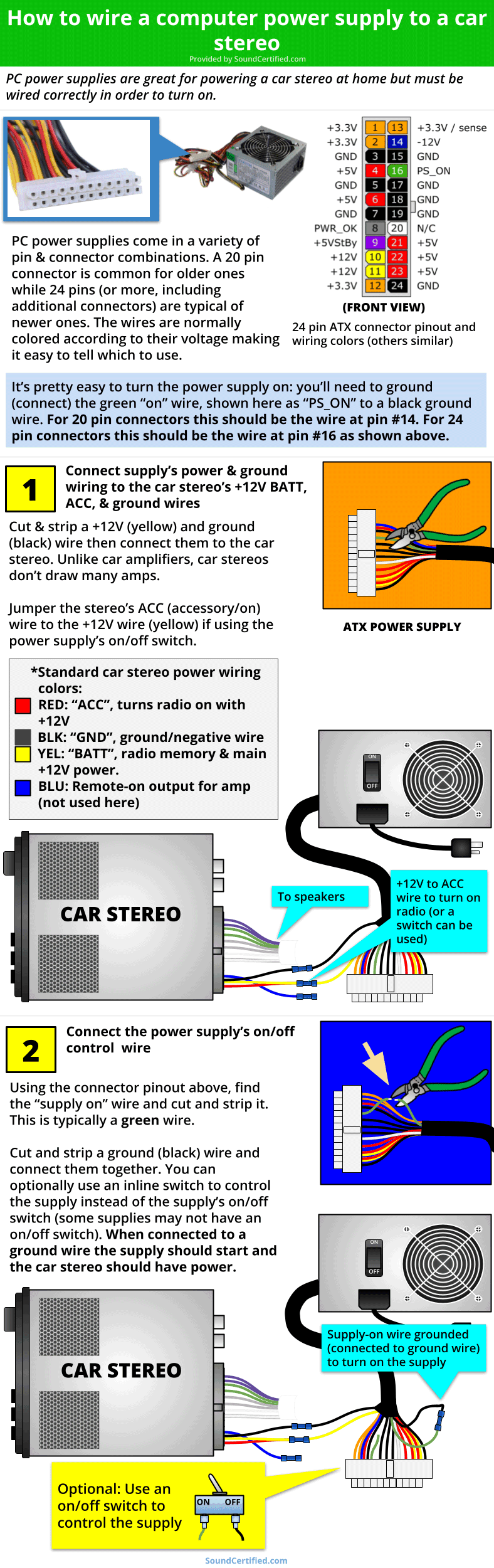
Using an ATX (desktop computer) power supply for a car stereo isn’t hard – in fact, you only need a few steps:
- Power connections: Cut a +12V wire (yellow) and a ground (black) wire from the main connector. Strip the insulation to leave about 3/8″ to 1/2″ bare wire. Use a crimp connector, solder, or another connector type to join the power supply’s +12V output (yellow) to the radio’s +12V battery wire (yellow). Do the same for the ground wires (black).
- Supply on control: PC supplies don’t turn on even if the on/off switch on the case is used. A PC motherboard uses a control signal to the “supply on” wire pin. To do the same, you’ll need to find, cut, and jumper this control signal wire to a ground wire either directly or with an on/off switch if you like [See diagram above]
- Radio accessory wire: Connect the radio’s accessory/on wire (red) to the +12V power wire from the supply either directly or you can use an on/off switch if you like.
Once you’ve connected the +12V and ground wiring to the radio, connect the “supply on” wire shown above to another ground wire as shown. The supply should start and your car radio should turn on.
As I mentioned earlier, switching off the power supply will cause the radio to lose its “memory” (settings, last station you played, etc) so you may find it easier to use an on/off switch on the accessory wire or turn the radio on & off using the power button.
Don’t forget that a radio uses only a tiny bit of power when turned off so you can leave your power supply running if you like. However, there’s another approach you can use as you’ll see next.
How to wire a car stereo and DC power supply to avoid losing memory presets

Wiring a car stereo up in your home is great, but one of the “gotchas” you’ll run into is losing all your radio presets and memory if power is completely removed. I’ve gotten several emails or comments from readers about this topic, in fact.
To wire your car stereo head unit in such a way you can keep the memory backup wire (+12V BATT wire) live when the main AC-DC power supply is off, you’ll need just a few things:
- One or more low-ampere power sources to supply the radio memory wire. This can be a small 12V AC-DC adapter, a miniature 12V battery, or both.
- Diodes to the power supplies from backfeeding to each other.
- A small amount of wire (18AWG or 20AWG even is fine – large wire isn’t needed here).
The diodes needed, how they work, and why they’re necessary
You’ll need one diode to isolate the main supply (5 amps or better is probably fine for most head units, but check your car stereo’s max. current draw in the specs to be sure) and one rated about 0.5A to 1A for each backup power source.
Some good examples of a 1A diode are part number 1N4007, although many others will work if they’re rated for 1A or higher.
TIP: If finding a single higher-rated diode to use on the main supply is a hassle or pricy, here’s a trick: you can use multiple diodes of a lower rating wired in parallel to replace a single one. As long as the total current rating is the same or higher, you can replace a single one with several.
This is especially helpful because diodes are often sold in packs of 2, 5, 10, etc. This means you can buy just one pack of the same value to use.
Why are diodes necessary to prevent back feeding voltage?
The problem with connecting multiple power supplies together at their outputs is that if another more powerful supply (like the main one) is live and connected to them, the voltage can “back feed”, or flow in reverse, to another power source. This can cause permanent damage and other odd problems.
Diodes act as an electrical one-way valve by allowing electrical current to flow in only one direction. By using one on each power supply wire to the radio’s memory, we can isolate each one from the other and prevent it from happening. Diodes have an anode side (the first end, no stripe) and a cathode side (the striped end). Current flows in a diode from anode to cathode and will not flow in reverse.
Always be sure to follow the example diagram and observe how the striped ends are connected.
Connecting the head unit to a backup power source
If you can leave a small AC/DC supply in use nearby when the main supply is switched off, that’s really all you’ll need. A small battery can be added however if you’d like to make sure there’s no momentary power loss or if you’re building a portable car stereo audio system, for example.
The battery will let you retain the presets & backup memory until you’re able to plugin another power supply. Note that small power supplies won’t run up your electrical bill because the car stereo only needs a very tiny amount of current for its memory if wired properly: less than 100mA usually.
Some example battery options you could use are:
- Home/building alarm system backup 12V batteries
- Motorcycle, lawnmower, and other small outdoor vehicle 12V batteries
- Two 6V batteries connected in series (this will provide 12V total)
- A 5V to 12V miniature step-up supply connected to a USB external battery pack.
Most car stereos need a memory wire voltage that’s close to 11 volts or higher to avoid losing what is stored in memory. Below that they can begin to lose settings and saved presets – it depends on how the particular car stereo model behaves.
Use a common ground connection
When using multiple voltage sources like this, be sure to connect all ground wires together at some point. This is necessary because a power supply’s voltage is supplied relative to ground. In other words, if we’re powering something, it’s due to the positive side having voltage potential relative to a ground wire at some point.
When the grounds aren’t correctly connected this can cause some strange issues or a power failure altogether. Once you’ve wired everything up, an easy way to check this is by using a test meter set to Ohms or continuity.
With one probe held at the negative terminal on the main supply, touch every other item’s ground wire. When everything’s properly connected, you’ll measure right at zero Ohms at each ground wire.
How to connect car stereo wires together properly
You’ve got several options for how to connect car stereos wires together properly. I’ll cover a few here. These are:
- Using the twist-and-tape method (not something I recommend, but it works “in a pinch”)
- Using connectors such as crimp (“butt”) connectors or wire nuts
- Soldering the wires together
I’ll cover each in detail.
1. Connecting wire using the twist-and-tape method
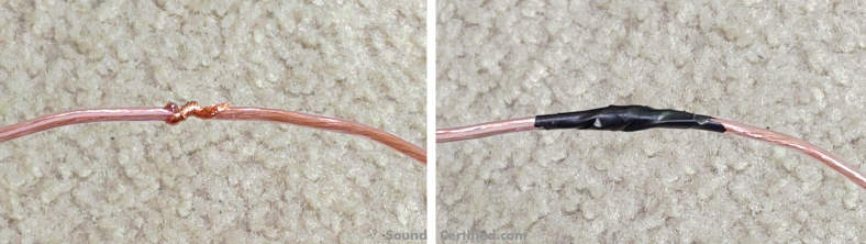
Although it’s easy to do and cheap (especially if you don’t have many tools around), it’s the least reliable way to connect speaker or car stereo wires together. In my experience, the tape can come off later or the twisted wire may work its way loose at some point.
It’s as easy to do as:
- Strip about 1/2 inch insulation from the end of each wire
- Twist the bare wire together as tightly as possible, wrapping around each other to help hold them together
- Tear off some electrical tape and tightly wind it around the exposed wire and also the wire insulation
2. Connecting wire using crimp connectors
This is one of the most reliable ways to connect wire and one I’ve used for years for car stereo installations. You’ll need one or more tools to strip your wire and crimp the connectors.
Here’s how:
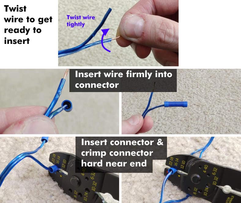
- Strip the wire leaving 3/8″ to 1/2″ bare wire exposed.
- Tightly twist the wire so it can be pushed into the connector properly.
- Insert the wire into one end firmly, pushing it into the metal contact inside. Be sure to insert it fully.
- Place the connector into the crimp tool in the appropriate position in the tool, near the end of the connector.
- Crimp very hard with the tool to make press the connector down hard, holding the wire inside permanently.
- Repeat the same for the other side & you other wires as needed.
Tip: For best results, once you’re done pull gently on the wire while holding the connector. The wire shouldn’t come out. If it does, you’ve crimped it poorly and will need to do it over again.
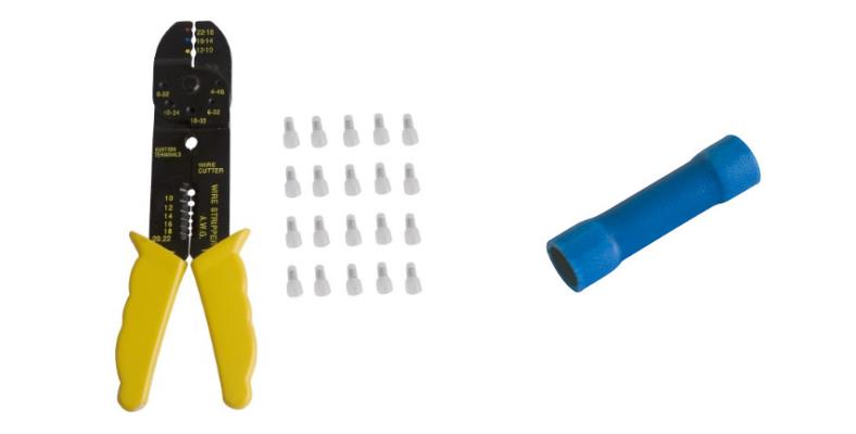 Examples of a wire crimping & stripping tool and crimp (“butt”) connectors. Blue is one of the most common and works well with 18AWG wire.
When shopping for crimp connectors you’ll notice they’re available in different colors for different gauges of wire. In most cases, the blue ones are fine for car speaker & radio wiring use. You can also pick up an affordable set that includes the crimp tool and connectors as well.
3. Connecting wire by soldering

This is hands-down the most reliable way to extend & splice wires as when done properly soldered wire is extremely strong and is permanent.
How to solder car stereo wires
- Cut & strip the wire (at least 1/2″ length of bare wire is needed).
- Hold up both ends to form an “X” shape with the wire facing opposite directions.
- Hold both ends and tightly twist each end around the other until they’re completely wrapped over each other.
- After the soldering iron is hot, apply heat to the wire with the tip. Once heated (after a few seconds usually), apply solder enough so that it has flowed fully through the wire.
- Rotate the wire to the other side and apply the solder until all of the wire is fully saturated with solder.
- Allow the wire to cool for a few moments.
- Tear 2 short pieces of electrical tape. Starting at the insulation and at an angle, tightly wrap the tape until it is fully covered.
It’s important to fully cover the wire once you’re done. That’s to prevent adjacent wires from touching each other and causing a short circuit that can permanently damage the radio’s output stages.
How long does soldering speaker wire properly take?
All in all, you’ll need about 30 minutes to solder a full set of car radio power & speaker wires or a bit less if you’re only connecting the power side.
Hi Marty.
Thank you for these guidelines, it really helped me start my own Head Unit project.
Please my Head Unit has 4 speakers connected but I want to connect an amplifier an utilize all the four speakers.
My Challenge
1. Connecting all the 4 sound/speaker output to the amp input and hook all 4 speakers to the amp (Please which Amp would you recommend I use or are there any other options)
2. I found this on AliExpress (AIYIMA TPA3116 5.1 Digital Amplifier Board 6 Channel AMP 2x100W 4x50W High Power Sound Amplifiers Board For 5.1 Home Theater DIY), is it Ok?
Hello, Victor. I am happy to hear that it helped you. :)
1. You can use any amplifier if you have line level connections. If your head unit does not have RCA outputs, you can use line level converters like these to connect to the amplifier inputs.
2. Yes, for indoor use that type of amplifier can work fine.
Best regards and have a nice weekend.
Thank you for your feedback.
I went back to the drawing board and I am a bit confuse so please help clarify this for me.
My setup looks similar to the Example 3 shown in the images on this page under “How to wire a car stereo at home(power + speaker wiring)”
https://soundcertified.com/wp-content/uploads/2020/09/car-stereo-home-use-wiring-diagram.webp
Kindly help illustrate how I can put the Amp in between the head unit and the speakers.
Also, Looking at things, the Amp I state earlier has a required DC of 18-25V but am using an ATX psu so am not sure if that will power the amp as well.
Thank You and have a nice weekend too.
Hello Victor. You can’t use the ATX power supply with the amplifier you have. It requires its own power supply with the correct voltage, and you’ll have to connect the ground terminal of the amp or its power supply to one of the ground wires of the ATX power supply.
It would be better if you use a 12V-compatible ampliifier instead, as you can use only one power suply and it will make things easier.
Your second option would be to use the ATX supply and get a step-up DC-DC supply which can step up the 12V from the ATX supply to the 18-25V required, but using a 12V amplifier would be better. In either case, you will need a line level converter if your head unit does not have RCA outputs.