Speaker Ohms & impedance can definitely be a confusing and sort-of mysterious topic. I’d love to help clear it all up for you!
How does speaker impedance compare to frequency response? What is speaker impedance exactly? And what other things do you need to know?
I’ll explain it all in plenty of detail with helpful diagrams and images along the way. By the time you’re done reading you’ll have a nearly expert understanding!

Contents
What is speaker impedance? Speaker impedance explained
Speaker impedance, measured in Ohms, is the voice coil total resistance to the flow of electric current as it operates with a musical signal.
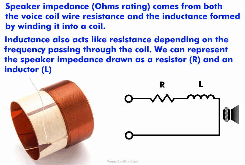
Speaker impedance is the total sum of two things:
- The resistance of the long winding of wire making up the voice coil.
- A special magnetic property called inductance created when the wire is wound into a coil.
An amp or stereo requires some amount of speaker load impedance to restrict how much electrical current the tries to provide just like with a resistor used in electronics with a power supply applied.
1. Voice coil resistance
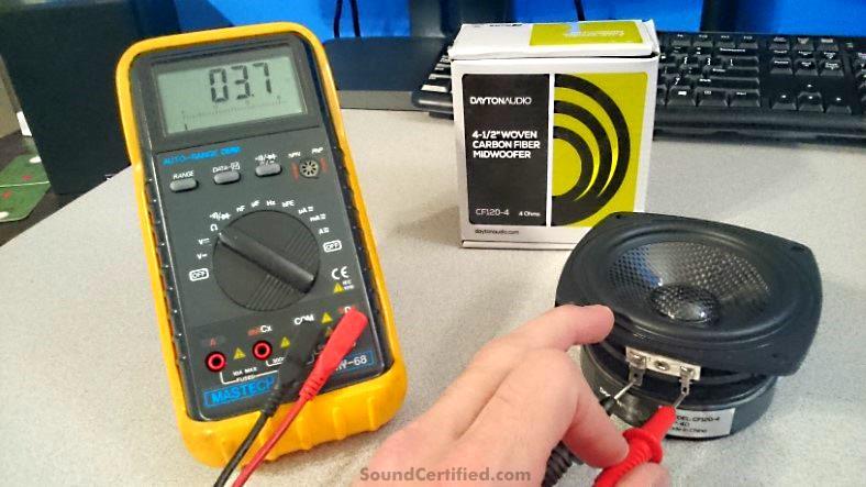
In the photo above, I’m measuring the impedance of a 4Ω speaker and my digital meter displays its resistance value. In this case that’s close to but not exactly 4Ω.
As they’re made of a long length of wire, a speaker’s voice coil has some value of resistance due to the wire itself. This is usually just a few ohms. When measuring a speaker’s impedance with a test meter you’ll be measuring the direct current (DC) resistance, not the inductance which won’t be present without an alternating current (AC) signal applied.
2. Inductance in a voice coil
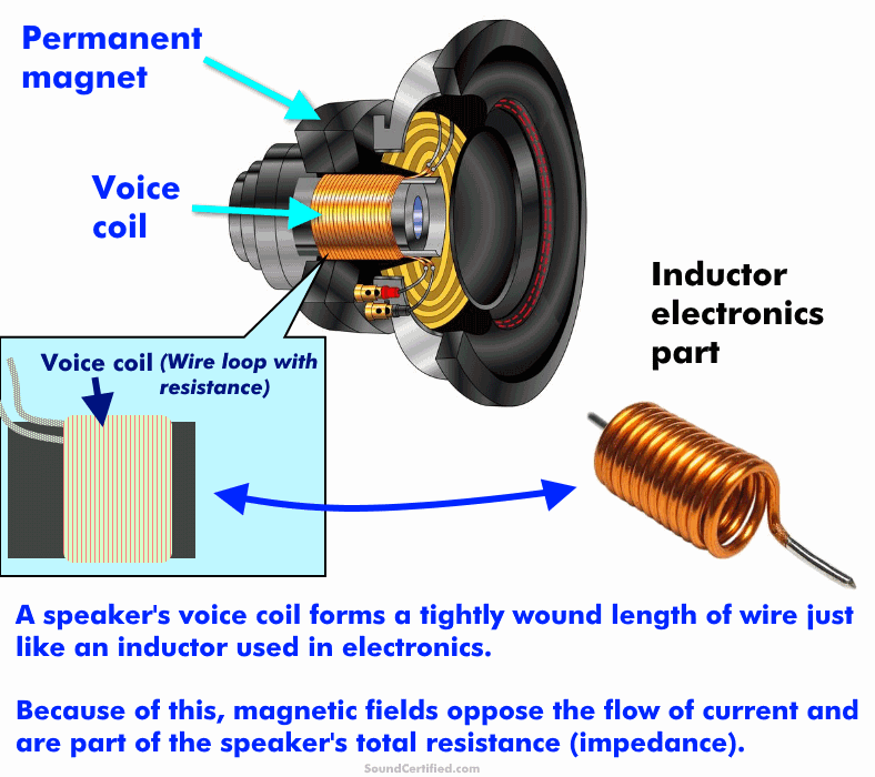
When an alternating signal is applied to the voice coil from a radio or amplifier, the wire winding that forms a coiled loop has an electrical property called inductance. This is unlike a straight wire that goes from point “a” to point “b.”
This inductance opposes the flow of electricity similar to resistance and changes with the audio frequency. This property that’s like resistance and present in inductors is called inductive reactance.
When we talk about the impedance of a speaker, most of the time we’re referring to the category (general Ohms range) of the speaker as used to match home or car stereo amplifiers.
What is the relationship between impedance and frequency?
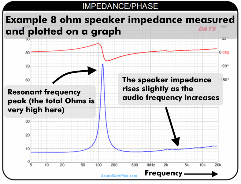
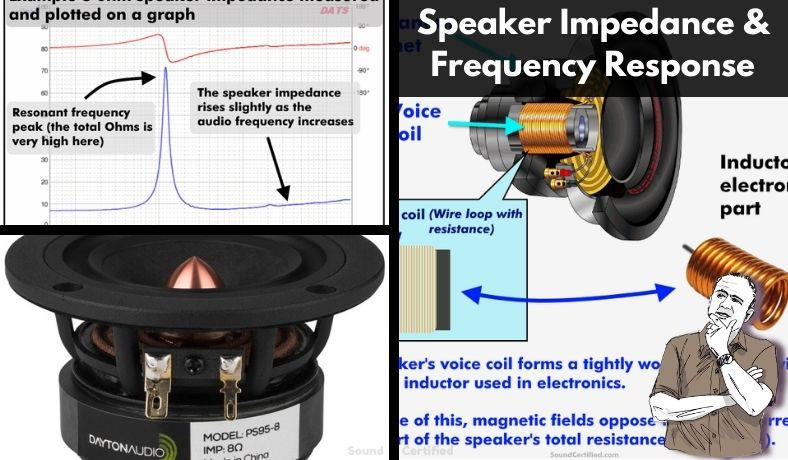
Example diagram of the impedance curve measured for an 8Ω midrange speaker. Notice how the impedance rises as the frequency increases. This due to the inductance of the voice coil. Inductive reactance (impedance) is directly related to the frequency.
Speaker impedance vs frequency
There’s a direct relationship between frequency and impedance:
- As the frequency increases, the inductive reactance increases, meaning the speaker impedance increases.
- As the frequency decreases, the inductive reactance decreases, meaning the speaker impedance decreases back toward the DC resistance of the speaker coil.
In other words, the impedance is directly proportional to the frequency, meaning it goes up or down as the frequency increases or decreases. Impedance isn’t the simple addition of the coil wire resistance and the inductance but rather the geometric sum of the two as you’ll see below.
Note that the total speaker impedance will always be equal to or greater than the voice coil resistance. It’s not possible to have zero ohms speaker impedance (at least not without a short circuit) or negative impedance – that wouldn’t make sense.
Calculating speaker impedance vs frequency
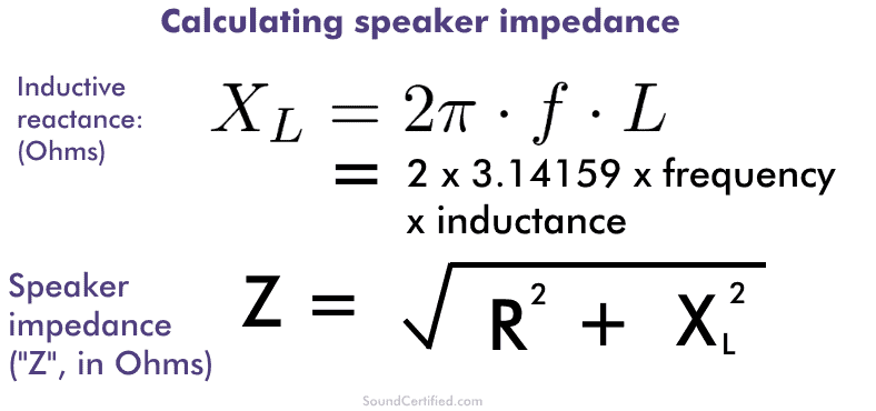
As you can see above, the inductive reactance (commonly written as “Xl” for inductance) is directly related to the frequency (“f” in the formula above). Also, you can see how the speaker impedance, in Ohms, is the square root of the sum of the squares of both the resistance and the inductive reactance of the speaker.
That’s because impedance is a property of physics that behaves differently than direct current resistance – they never add together directly. Think of it as trigonometry and the way you find the hypotenuse of a triangle.
How does speaker impedance compare to frequency response?
Generally speaking, there’s little, if any, relationship between impedance and the frequency response. However, it depends on the particular speaker. Some may be influenced more than others but generally speaking, other than at the resonant frequency of a speaker the frequency response doesn’t have any real bearing on it.
A speaker’s frequency response is the end result of its design, how well the magnet/cone/suspension assembly performs, and a variety of other parameters like that.
Note that at the resonant frequency the impedance is typically very high due to resonance as that’s when the speaker assembly can’t remain stable for that very small frequency range. However, it’s a rather fringe situation and generally speaking speaker designers avoid having speakers play near their resonant frequency anyhow.
What frequency determines speaker impedance?
There isn’t normally a frequency used to determine speaker impedance. Instead, the manufacturer’s listed impedance, in Ohms, is approximately the average in its normal operating range.
Other parameters like efficiency (measured speaker output in decibels [dB] for 1 watt typically) and off-axis response are usually measured at 1 kiloHertz (KHz). That’s not the case impedance, as it wouldn’t really make sense.
For some particular speakers with additional data, there might be an impedance value specified for a specified frequency. However, if that’s included it’s usually provided as a graph. In that case, the impedance is shown as a graph over a wide range of audio frequencies.
Does Speaker impedance affect sound quality?
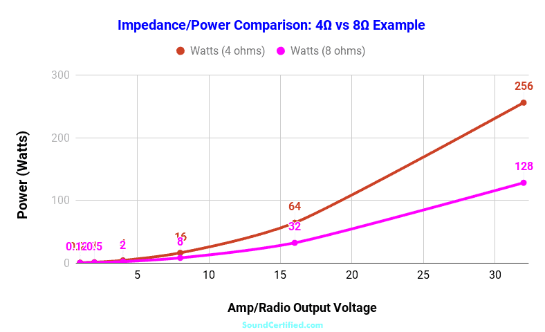
A graph comparing the power produced by 8 and 4 ohm speakers when connected to the same amplifier. A speaker with an 8 ohm impedance consumes less power at the same output (volume) as a speaker with a 4 ohm impedance when connected to the same amplifier (the same output voltage).
Only certain impedance-related factors, such as speaker power (volume) and how they work with crossovers, have an effect on music. In the vast majority of cases, higher ohms does not mean better sound quality.
The best sound comes from using the right speaker impedance for the right application:
- Matching the correct speaker Ohms to your radio or amp for the best available power and volume.
- When using speaker crossovers, using the correct speaker impedance.
How speaker impedance affects power and volume
The graph above shows an example of the power produced by an 8 ohm speaker when used on the same amplifier as a 4 ohm speaker.
- The power for the lower impedance speaker, at the same amplifier or stereo output level, is twice that of the 8 ohm speaker.
- The maximum power you’ll get for an 8 ohm speaker connected to a 4 ohm rated amp will always be lower than that of using a 4 ohm speaker.
For example, using a 16Ω speaker in place of an 8Ω one for an 8Ω rated stereo has disadvantages in power loss and volume. There’s nothing to be gained from doing it. (Likewise the same principle for 8Ω and 4Ω speakers, too). For two otherwise identical speakers, the sound quality itself will be the same – but the one with the higher impedance will have a lower volume since it will have less power across it due to lower electrical current.
How does speaker impedance affect crossover frequencies?
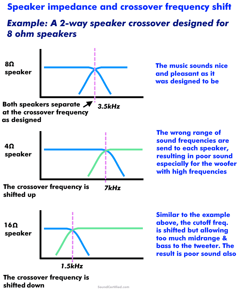
Crossovers are designed to work only with a particular speaker impedance. When the wrong Ohms load is used a “crossover shift” occurs, meaning the crossover frequency changes and the sound suffers.
Can I use different speaker impedances with a crossover? What is crossover shift?
Passive (non-powered) speaker crossovers are basically a type of filter designed around a certain speaker impedance (Ohms) load being used. They work using capacitors and inductors which can be used to eliminate certain undesired sections of sound frequency from being sent to a speaker. When combined together they can be used to create a great-sounding speaker system with much better clarity and lower distortion thanks to the crossover frequency used.
Changing the speaker impedance connected to a crossover alters the crossover frequency. This is called crossover shift and results in poor sound because the frequency is shifted quite a bit.
Some of the audio side effects of crossover shift are:
- A “harsh” sound from woofers or midrange speakers. Tweeters may sound distorted and begin to “break up” at a lower volume than they used to.
- A “thin”, weak quality to the music.
- Gaps in the sound ranges you should be hearing.
Speaker crossovers should only be used with their intended speaker impedance. Otherwise you’ll have poor sound and poor performance.
For example, you can’t use 8Ω speakers with a crossover designed for 4Ω ones or vice-versa.